
Datasheet


257 PRM-SI
www.vishay.com
Vishay BCcomponents
Revision: 05-Jun-2020
3
Document Number: 28460
For technical questions, contact: aluminumcaps2@vishay.com
THIS DOCUMENT IS SUBJECT TO CHANGE WITHOUT NOTICE. THE PRODUCTS DESCRIBED HEREIN AND THIS DOCUMENT
ARE SUBJECT TO SPECIFIC DISCLAIMERS, SET FORTH AT www.vishay.com/doc?91000
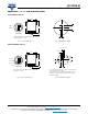
DIMENSIONS in millimeters AND AVAILABLE FORMS
TWO TERMINAL SNAP-IN
Fig. 2 - Two terminal snap-in Fig. 3 - Mounting hole diagram
THREE TERMINAL SNAP-IN
Fig. 4 - Three terminal snap-in Fig. 5 - Mounting hole diagram
+ Terminal
- Terminal
L
Bottom view
5.8 mm
+ 0
- 1
Ø D
L + 2 max.
The minus terminal can be marked with a black dot or
with an imprinted “-” sign.
Ø 2 ± 0.1 (2 x)
10
± 0.1
Ø D
L + 2 max.
4 ± 0.5
L
The negative terminal has TWO pins which are BOTH
electrically connected.
Bottom view
Minus pole
marking
+ Terminal
- Terminal
Ø 2 ± 0.1 (2 x)
Ø 2.5 ± 0.1
3.3 ± 0.1
4.75 ± 0.1
10 ± 0.1
The 10 mm spacing of the 2 pin snap-in is used as the base
layout and a third hole is added.
The third hole is closer to the negative primary hole so that
polarization is always maintained, together with added
mechanical stability.