
Datasheet


NTCALUG01T
www.vishay.com
Vishay BCcomponents
Revision: 25-Apr-2019
1
Document Number: 29164
For technical questions, contact: nlr@vishay.com
THIS DOCUMENT IS SUBJECT TO CHANGE WITHOUT NOTICE. THE PRODUCTS DESCRIBED HEREIN AND THIS DOCUMENT
ARE SUBJECT TO SPECIFIC DISCLAIMERS, SET FORTH AT www.vishay.com/doc?91000
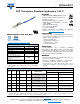
NTC Thermistors, Standard Lug Sensors, 150 °C
DESIGN SUPPORT TOOLS AVAILABLE
• NTC curve computation:
www.vishay.com/thermistors/ntc-curve-list/
Note
(1)
Other R
25
-values, B
25/85
-values, and tolerances are available
upon request
FEATURES
• 150 °C long term stability (5000 h dry heat)
• Easy mounting using ring tongue terminal
• Rugged construction
• Cable with ETFE insulation according to
NEMA HP-3, type Z, rated 600 V
RMS
, cable test
voltage 3.4 kV
• AEC-Q200 qualified (grade 1)
• UL recognized, file E148885
(UL category XGPU2)
• Material categorization: for definitions of compliance
please see www.vishay.com/doc?99912
APPLICATIONS
• Suitable for surface sensing applications, especially when
a good electrical insulation and a good thermal contact
with the chassis is required for:
- Automotive equipment
- EV and battery management
- Power electronics, heat sink
- Consumer appliances
DESCRIPTION
A NTC thermistor chip is soldered to AWG#26
multi-stranded silver plated copper leads with ETFE
insulation and insulated with epoxy coating. The insulated
sensor is attached to a tin plated copper ring lug via a middle
buffer layer. The lead wires are twisted.
MOUNTING
• By means of M3 (Stud #3, #4) or M3,5 (Stud #5, #6) screw.
Leads to be soldered or crimped
• The device is suitable for screwing e.g. on metal surface
• The leads are suitable for soldering e.g. on PCB
• Consult Vishay for other cable length, cable section,
screw sizes, insulation, connector crimping or other
features
Note
(1)
RoHS exemption 7(c)-I: electrical and electronic components containing lead in a glass or ceramic other than dielectric ceramic in
capacitors, e.g. piezo-electronic devices, or in a glass or ceramic matrix compound
QUICK REFERENCE DATA
PARAMETER VALUE UNIT
Resistance value at 25 °C
(1)
10K
Tolerance on R
25
-value
(1)
± 1 to ± 2 %
B
25/85
-value
(1)
3435, 3984 K
Tolerance on B
25/85
-value ± 0.5 to ± 1 %
Operating temperature range
at zero dissipation
-40 to +150 °C
Min. dielectric withstanding
voltage between terminals
and lug
2700 V
AC
Min. insulation resistance between
terminals and lug at 500 V
DC
100 M
Weight 2.0 to 3.2 g
3
3
D
D
3
D
3D Models
Design Tools
Available
ELECTRICAL DATA AND ORDERING INFORMATION
R
25
()
R
25
-TOL.
(± %)
B
25/85
(K)
B
25/85
-TOL.
(± %)
L
1
(mm)
DESCRIPTION
SAP MATERIAL AND ORDERING NUMBER
with RoHS exemption
(1)
without RoHS exemption
(1)
10 000 1 3984 0.5 150 ± 10
NTC Lug01T 10K 1 % 3984 K
150 °C ETFE AWG26 150 mm
NTCALUG01T103F NTCALUG01T103FA
10 000 1 3435 1.0 150 ± 10
NTC Lug01T 10K 1 % 3435 K
150 °C ETFE AWG26 150 mm
NTCALUG01T103FL NTCALUG01T103FLA
10 000 2 3984 0.5 40 ± 5
NTC Lug01T 10K 2 % 3984 K
150 °C ETFE AWG26 40 mm
NTCALUG01T103G400 NTCALUG01T103G400A
10 000 2 3984 0.5 150 ± 10
NTC Lug01T 10K 2 % 3984 K
150 °C ETFE AWG26 150 mm
NTCALUG01T103G NTCALUG01T103GA
10 000 2 3984 0.5 200 ± 10
NTC Lug01T 10K 2 % 3984 K
150 °C ETFE AWG26 200 mm
NTCALUG01T103G201 NTCALUG01T103G201A
10 000 2 3984 0.5 500 ± 10
NTC Lug01T 10K 2 % 3984 K
150 °C ETFE AWG26 500 mm
NTCALUG01T103G501 NTCALUG01T103G501A