
Datasheet

NTCS0402E3.....T
www.vishay.com
Vishay BCcomponents
Revision: 13-Dec-2018
2
Document Number: 29003
For technical questions, contact: nlr@vishay.com
THIS DOCUMENT IS SUBJECT TO CHANGE WITHOUT NOTICE. THE PRODUCTS DESCRIBED HEREIN AND THIS DOCUMENT
ARE SUBJECT TO SPECIFIC DISCLAIMERS, SET FORTH AT www.vishay.com/doc?91000
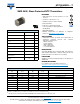
DIMENSIONS in millimeters
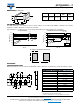
SOLDERING CONDITIONS
This SMD thermistor is only suitable for wave or reflow soldering, in accordance with JEDEC
®
J-STD-020. The maximum
temperature of 260 °C during 40 s should not be exceeded.
Typical examples of a soldering processes that will provide reliable joints without damage, are shown below.
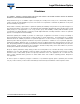
PACKAGING
TAPE SPECIFICATIONS
All tape specifications are in accordance with IEC 60286-3. Basic dimensions are given below. Carrier tape material is paper.
Notes
(1)
Measured 0.3 mm above base pocket
(2)
P
0
pitch cumulative error over any 10 pitches ± 0.2 mm
T
L
1
W
L
2
L3
L4
L
1
WT
L
2
AND L
3
MIN.
L
4
MIN.
1.0 ± 0.15 0.5 ± 0.15 0.5 ± 0.15 0.1 0.3
Time (s)
0
50 100
150 200
200
250
100
150
Temperature (°C)
50
0
300
250
260 °C
≈ 245 °C
215 °C
180 °C
130 °C
2 K/s
40 s
10 s
10 s
Reflow Soldering
Lead (Pb)-free Reflow Solderin
g Profile
260 °C
≈ 245 °C
235 °C
≈ 170 °C
≈ 120 °C
2 K/s
max.
Time (s)
0
50 100
150 200
350
200
250
100
150
Temperature (°C)
50
0
300
40 s max.
≈ 60 s
20 s min.
normal
limit
250
300
6 K/s
max.
1.5
0.5
0.5
Recommended solder land pattern dimensions (mm)
F
W
P
0
P
2
D
0
B
0
A
0
P
1
E
1
JWB288
T
T
1
DIMENSIONS OF PAPER TAPE in millimeters
PARAMETER DIMENSION
A
0
(1)
0.65 ± 0.1
B
0
(1)
1.15 ± 0.1
W 8.0 ± 0.2
E
1
1.75 ± 0.1
F 3.5 ± 0.05
D
0
1.55 ± 0.05
P
0
(2)
4.0 ± 0.1
P
1
4.0 ± 0.1
P
2
2.0 ± 0.05
T tape thickness max. 0.8
T
1
cover tape thickness max. 0.1