
Datasheet


PR01/02/03
www.vishay.com
Vishay BCcomponents
Revision: 24-Jun-13
1
Document Number: 28729
For technical questions, contact: filmresistorsleaded@vishay.com
THIS DOCUMENT IS SUBJECT TO CHANGE WITHOUT NOTICE. THE PRODUCTS DESCRIBED HEREIN AND THIS DOCUMENT
ARE SUBJECT TO SPECIFIC DISCLAIMERS, SET FORTH AT www.vishay.com/doc?91000
Power Metal Film Leaded Resistors
DESCRIPTION
A homogeneous film of metal alloy is deposited on a high
grade ceramic body. After a helical groove has been cut in
the resistive layer, tinned connecting wires of electrolytic
copper or copper-clad iron are welded to the end-caps. The
resistors are coated with a red, non-flammable lacquer
which provides electrical, mechanical and climatic
protection. This coating is not resistant to aggressive fluxes
and cleaning solvents. The encapsulation is resistant to all
cleaning solvents in accordance with IEC 60068-2-45.
FEATURES
• High power in small packages (1 W/0207 size to
3 W/0617 size)
• Different lead materials for different
applications
• Defined interruption behaviour
• Technology: Metal film
• AEC-Q200 qualified (PR01 and PR02)
• Lead (Pb)-free solder contacts
• Pure tin plating provides compatibility with lead (Pb)-free
and lead containing soldering processes
• Material categorization: For definitions of compliance
please see www.vishay.com/doc?99912
APPLICATIONS
• All general purpose power applications
Notes
• R value is measured with probe distance of 24 mm ± 1 mm using 4-terminal method.
(1)
1 % tolerance is available for R
n
-range from 1 R upwards.
(2)
Ohmic values (other than resistance range) are available on request.
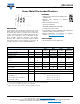
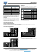
TECHNICAL SPECIFICATIONS
DESCRIPTION UNIT PR01
PR02
Cu-lead
PR02
FeCu-lead
PR03
Cu-lead
PR03
FeCu-lead
Resistance range
(2)
0.22 to 1M 0.33 to 1M 1 to 1M 0.68 to 1M 1 to 1M
Resistance tolerance % ± 1; ± 5 ± 1; ± 5 ± 1; ± 5 ± 1; ± 5 ± 1; ± 5
Resistance series ± 1 (E24, E96); ± 5 (E24 series)
(1)
Rated dissipation, P
70
1 R W1 21.332.5
R < 1 0.6 1.2 - 1.6 -
Thermal resistance (R
th
) K/W 135 75 115 60 75
Temperature coefficient ppm/K ± 250 ± 250 ± 250 ± 250 ± 250
Maximum permissible voltage
(U
max.
AC/DC)
V 350 500 500 750 750
Basic specifications IEC 60115-1
Climatic category (IEC 60068-1) 55/155/56
Stability after:
Load (1000 h, P
70
) R max.: ± (5 % R + 0.1 )
Long term damp heat test (56 days) R max.: ± (3 % R + 0.1 )
Soldering (10 s, 260 °C) R max.: ± (1 % R + 0.05 )