
Datasheet


PR01/02/03
www.vishay.com
Vishay BCcomponents
Revision: 24-Jun-13
11
Document Number: 28729
For technical questions, contact: filmresistorsleaded@vishay.com
THIS DOCUMENT IS SUBJECT TO CHANGE WITHOUT NOTICE. THE PRODUCTS DESCRIBED HEREIN AND THIS DOCUMENT
ARE SUBJECT TO SPECIFIC DISCLAIMERS, SET FORTH AT www.vishay.com/doc?91000
APPLICATION INFORMATION
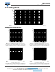
PR02 Temperature rise (T) at the lead end (soldering point)
as a
function of dissipated power at various lead lengths after mounting.
PR03 Temperature rise (T) at the lead end (soldering point)
as a
function of dissipated power at various lead lengths after mounting.
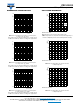
PR03 Temperature rise (T) at the lead end (soldering point)
as a
function of dissipated power at various lead lengths after mounting.
PR03 Hot-spot temperature rise (T) as a function
of dissipated power.
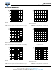
PR03 Hot-spot temperature rise (T) as a function
of dissipated power.
PR03 Hot-spot temperature rise (T) as a function
of dissipated power.
100
0 1.6 2.4
0
0.8
20
40
60
80
∆
T
(K)
P
(W)
15 mm
20 mm
25 mm
Ø 0.8 mm FeCu-leads
Minimum distance from resistor body to PCB = 1 mm
100
01 3
0
2
20
40
60
80
∆
T
(K)
P
(W)
15 mm
20 mm
25 mm
Ø 0.8 mm Cu-leads
Minimum distance from resistor body to PCB = 1 mm
100
01 3
0
2
20
40
60
80
∆
T
(K)
P
(W)
15 mm
10 mm
20 mm
25 mm
Ø 0.6 mm FeCu-leads
Minimum distance from resistor body to PCB = 1 mm
200
01 3
0
2
40
80
120
160
∆
T
(K)
P
(W)
Ø 0.8 mm Cu-leads
200
240
01 3
0
2
40
80
120
160
Δ
T
(K)
P
(W)
Ø 0.6 mm FeCu-leads
240
200
01
0
3 2
40
80
120
160
Δ
T
(K)
P
(W)
Ø 0.8 mm FeCu-leads