DATA SHEET GENERAL PURPOSE CHIP RESISTORS RC0805 (Pb Free) Product specification – Sep 03, 2004 V.
Product specification Chip Resistor Surface Mount RC SERIES 2 10 0805 (Pb Free) SCOPE This specification describes RC0805 series chip resistors with lead-free terminations made by thick film process. ORDERING INFORMATION Part number is identified by the series, size, tolerance, packing type, temperature coefficient, taping reel and resistance value.
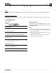
Product specification Chip Resistor Surface Mount RC SERIES 3 10 0805 (Pb Free) MARKING RC0805 E-24 series: 3 digits ynsc001 Fig. 1 Value=10 KΩ First two digits for significant figure and 3rd digit for number of zeros Both E-24 and E-96 series: 4 digits ynsc004 Fig. 2 Value=10 KΩ First three digits for significant figure and 4th digit for number of zeros For marking codes, please see EIA-marking code rules in data sheet “Chip resistors instruction”.
Product specification Chip Resistor Surface Mount RC SERIES ELECTRICAL CHARACTERISTICS FOOTPRINT AND SOLDERING PROFILES Table 2 RC0805 1/8 W CHARACTERISTICS Operating Temperature Range –55 °C to +155 °C Maximum Working Voltage 150 V Maximum Overload Voltage 300 V Dielectric Withstanding Voltage 300 V 5% (E24) 1 Ω to 22 MΩ Resistance Range 1% (E96) 1 Ω to 10 MΩ Zero Ohm Jumper < 0.
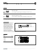
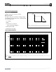
Product specification Chip Resistor Surface Mount RC SERIES 5 10 0805 (Pb Free) FUNCTIONAL DESCRIPTION POWER RATING MRA632 Pmax (%Prated) RC0805 rated power at 70°C is 1/8 W RATED VOLTAGE 100 The DC or AC (rms) continuous working voltage corresponding to the rated power is determined by the following formula: 50 V=√(P X R) 0 −55 0 155 100 Tamb (°C) 50 70 Where V=Continuous rated DC or AC (rms) working voltage (V) Fig.
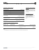
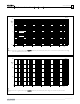
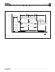
Product specification Chip Resistor Surface Mount RC SERIES 6 10 0805 (Pb Free) MBD588 10 3 P max (W) 10 2 10 single pulse t p /t i =1000 1 10 1 10 6 10 5 10 4 10 3 10 2 10 1 1 t i (s) Fig. 7 Pulse on a regular basis for type: RC0805; maximum permissible peak pulse power as a function of pulse duration for single pulse and repetitive pulse tp/ti = 1000 MLB722 600 Vmax (V) 400 200 0 10 6 10 5 10 4 10 3 10 2 10 1 t i (s) 1 Fig.
Product specification Chip Resistor Surface Mount RC 7 10 0805 (Pb Free) SERIES TESTS AND REQUIREMENTS Table 4 Test condition, procedure and requirements TEST Temperature Coefficient of Resistance (T.C.R.) TEST METHOD PROCEDURE REQUIREMENTS MIL-STD-202F-method 304; At +25/–55 °C and +25/+125 °C Refer to table 3 JIS C 5202-4.8 Formula: R2–R1 T.C.
Product specification Chip Resistor Surface Mount TEST Solderability Bending Strength Resistance to Solvent Noise RC SERIES TEST METHOD PROCEDURE REQUIREMENTS MIL-STD-202F-method 208A; Solder bath at 245±3 °C Well tinned (≥95% covered) IEC 60115-1 4.17 Dipping time: 2±0.5 seconds No visible damage Resistors mounted on a 90 mm glass epoxy resin PCB (FR4) ±(1.0%+0.05 Ω) for 1% tol. Bending: 5 mm No visible damage No smeared IEC 60115-1 4.
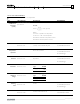
Product specification Chip Resistor Surface Mount 75 RC 80 − 98% RH 90 − 98% RH temperature [°C] SERIES 90 − 98% RH 9 10 0805 (Pb Free) 80 − 98% RH 90 − 98% RH initial drying 24 hours rate of change of temperature is unspecified, however, specimens shall not be subjected to radiant heating from chamber conditioning processes 50 end of final cycle; measurements as specified in 2.7 +10 °C (+18 °F) −2 °C (−3.6 °F) 25 initial measurements as specified in 2.2 0 temperature tolerance ±2 °C (±3.
Product specification Chip Resistor Surface Mount RC SERIES 10 10 0805 (Pb Free) REVISION HISTORY REVISION DATE CHANGE NOTIFICATION DESCRIPTION Version 2 Sep 03, 2004 - - Test method and procedure updated - PE tape added (paper tape will be replaced by PE tape) www.yageo.com Sep 03, 2004 V.