
Datasheet

Vishay Siliconix
SUD06N10-225L-GE3
Document Number: 62831
S13-0193-Rev. A, 28-Jan-13
www.vishay.com
1
This document is subject to change without notice.
THE PRODUCTS DESCRIBED HEREIN AND THIS DOCUMENT ARE SUBJECT TO SPECIFIC DISCLAIMERS, SET FORTH AT www.vishay.com/doc?91000
For technical questions, contact: pmostechsupport@vishay.com
N-Channel 100 V (D-S) MOSFET
FEATURES
• TrenchFET
®
Power MOSFETs
• Material categorization:
For definitions of compliance please see
www.vishay.com/doc?99912
Notes:
a. Surface mounted on 1" x 1" FR4 board.
b. See SOA curve for voltage derating.
PRODUCT SUMMARY
V
DS
(V) R
DS(on)
()I
D
(A) Q
g
(Typ)
100
0.200 at V
GS
= 10 V
6.5
2.7
0.225 at V
GS
= 4.5 V
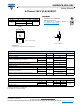
6
TO-252
SG
D
Top View
Drain Connected to Tab
Order Number:
SUD06N10-225L-GE3 (Lead (Pb)-free and Halogen-free)
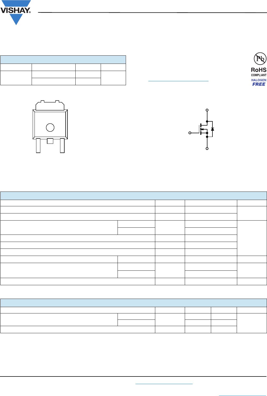
N-Channel MOSFET
G
D
S
ABSOLUTE MAXIMUM RATINGS (T
A
= 25 °C, unless otherwise noted)
Parameter Symbol Limit Unit
Drain-Source Voltage
V
DS
100
V
Gate-Source Voltage
V
GS
± 20
Continuous Drain Current (T
J
= 150 °C)
b
T
C
= 25 °C
I
D
6.5
A
T
C
= 125 °C
2.9
Pulsed Drain Current
I
DM
8
Continuous Source Current (Diode Conduction)
I
S
6.5
Avalanche Current
I
AR
5
Repetitive Avalanche Energy (Duty Cycle 1 %) L = 0.1 mH
E
AR
1.25 mJ
Maximum Power Dissipation
T
C
= 25 °C
P
D
16.7
b
W
T
A
= 25 °C
1.25
a
Operating Junction and Storage Temperature Range
T
J
, T
stg
- 55 to 150 °C
THERMAL RESISTANCE RATINGS
Parameter Symbol Typical Maximum Unit
Junction-to-Ambient
a
t 10 sec
R
thJA
40 50
°C/W
Steady State
80 100
Junction-to-Case
R
thJC
67.5