
Datasheet


Document Number: 83787 For technical questions, contact: sensorstechsupport@vishay.com
www.vishay.com
Rev. 1.5, 17-Aug-09 3
TCST5250
Transmissive Optical Sensor with
Phototransistor Output
Vishay Semiconductors
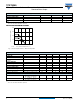
Fig. 2 - Test Circuit for t
on
and t
off
Fig. 3 - Switching Times
BASIC CHARACTERISTICS
T
amb
= 25 °C, unless otherwise specified
Fig. 4 - Forward Current vs. Forward Voltage
Fig. 5 - Relative Current Transfer Ratio vs. Ambient Temperature
Fig. 6 - Collector Dark Current vs. Ambient Temperature
Fig. 7 - Collector Current vs. Forward Current
Channel I
Channel II
20223
+ 5 V
I
C
= 1 mA;
adjusted by I
I
F
0
I
F
R
G
= 50 Ω
t
p
t
p
T
= 0.01
Oscilloscope
R 1 MΩ
L
≥
C
L
≤ 20 pF
50 Ω 100 Ω
= 50 µs
F
t
p
t
t
0
0
10 %
90 %
100 %
t
r
t
d
t
on
t
s
t
f
t
off
I
F
I
C
t
p
Pulse duration
t
d
Delay time
t
r
Rise time
t
on
(= t
d
+ t
r
) Turn-on time
t
s
Storage time
t
f
Fall time
t
off
(= t
s
+ t
f
)Turn-off time
96 11698
0.1
1
10
100
1000
0
V
F
- Forward Voltage (V)
96 11862
I
F
- Forward Current (mA)
1.6
0.2
1.4
1.2
1.0
0.80.6
0.4
2.0
1.8
- 25
0
0.5
1.0
1.5
2.0
CTR
- Relative Current Transfer Ratio
rel
T
amb
- Ambient Temperature (°C)
95 11089
V
CE
= 5 V
I
F
= 20 mA
100
75
50
25
0
0
1
10
100
1000
10 000
I - Collector Dark Current (nA)
CEO
T
amb
- Ambient Temperature (°C)
95 11090
V
CE
= 25 V
I
F
= 0 A
100
75
50
25
0.1
0.001
0.01
0.1
10
I - Collector Current (mA)
C
I
F
- Forward Current (mA)
95 11083
1
V
CE
= 10 V
100 10
1