
Datasheet


Typical Performance Characteristics
www.vishay.com
Vishay Sprague
Revision: 07-Feb-2019
3
Document Number: 40215
For technical questions, contact: tantalum@vishay.com
THIS DOCUMENT IS SUBJECT TO CHANGE WITHOUT NOTICE. THE PRODUCTS DESCRIBED HEREIN AND THIS DOCUMENT
ARE SUBJECT TO SPECIFIC DISCLAIMERS, SET FORTH AT www.vishay.com/doc?91000
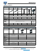
ENVIRONMENTAL PERFORMANCE CHARACTERISTICS
ITEM CONDITION POST TEST PERFORMANCE
High temperature
exposure (storage)
MIL-STD-202, method 108
1000 h, at maximum rated temperature,
unpowered
Capacitance change
Dissipation factor
Leakage current
ESR
Within ± 20 % of initial value
Initial specified limit
Initial specified limit
Initial specified limit
Operational life test
at +125 °C
AEC-Q200
1000 h application 2/3 of rated voltage
Capacitance change
Dissipation factor
Leakage current
ESR
Within ± 20 % of initial value
Initial specified limit
Shall not exceed 10 times the initial limit
Initial specified limit
Operational life test
at +150 °C (for TH3)
and at +175 °C
(for TH4)
AEC-Q200
1000 h application 1/2 of rated voltage
Capacitance change
Dissipation factor
Leakage current
ESR
Within ± 20 % of initial value
Shall not exceed 3 times the initial limit
Shall not exceed 10 times the initial limit
Shall not exceed 3 times the initial limit
Surge voltage MIL-PRF-55365:
1000 successive test cycles at 85 °C of surge
voltage (as specified in the table above), in
series with a 33 resistor at the rate of
30 s ON, 30 s OFF
Capacitance change
Dissipation factor
Leakage current
ESR
Within ± 30 % of initial value
Shall not exceed 1.5 times the initial limit
Shall not exceed 2 times the initial limit
Shall not exceed 1.5 times the initial limit
Biased humidity test AEC-Q200
At 85 °C / 85 % RH, 1000 h,
with rated voltage applied
Capacitance change
Dissipation factor
Leakage current
ESR
Within ± 20 % of initial value
Shall not exceed 3 times the initial limit
Shall not exceed 10 times the initial limit
Shall not exceed 3 times the initial limit
Temperature cycling AEC-Q200 / JESD22, method JA-104
-55 °C / +125 °C, for 1000 cycles
Capacitance change
Dissipation factor
Leakage current
ESR
Within ± 20 % of initial value
Initial specified limit
Initial specified limit
Initial specified limit
MECHANICAL PERFORMANCE CHARACTERISTICS
ITEM CONDITION POST TEST PERFORMANCE
Vibration MIL-STD-202, method 204: 10 Hz to 2000 Hz, 5 g
peak for 20 min, 12 cycles each of 3 orientations
(total 36 cycles), at rated voltage
Capacitance change
Dissipation factor
Leakage current
Within ± 20 % of initial value
Initial specified limit
Initial specified limit
There shall be no mechanical or visual damage to
capacitors post-conditioning.
Mechanical shock MIL-STD-202, method 213, condition F, 1500 g peak,
0.5 ms, half-sine
Capacitance change
Dissipation factor
Leakage current
Within ± 20 % of initial value
Initial specified limit
Initial specified limit
There shall be no mechanical or visual damage to
capacitors post-conditioning.
Resistance
to solder heat
MIL-STD-202, method 210, condition D
Solder dip 260 °C ± 5 °C, 10 s
Capacitance change
Dissipation factor
Leakage current
Within ± 20 % of initial value
Initial specified limit
Initial specified limit
Resistance to
solvents
MIL-STD-202, method 215 Capacitance change
Dissipation factor
Leakage current
Within ± 20 % of initial value
Initial specified limit
Initial specified limit
There shall be no mechanical or visual damage to
capacitors post-conditioning.
Body marking shall remain legible.
Solderability AEC-Q200 / J-STD-002 Electrical test not required
Terminal strength /
Shear force test
AEC-Q200-006
Apply a pressure load of 17.7 N (1.8 kg) for 60 s
horizontally to the center of capacitor side body
Exception: for case size 0603 pressure load is 5N
Part should not be sheared off the pads and no body
cracking post-conditioning. Electrical test not required.
Flammability Encapsulation materials meet UL 94 V-0 with an
oxygen index of 32 %
n/a