TR3 www.vishay.
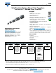
TR3 www.vishay.com Vishay Sprague DIMENSIONS in inches [millimeters] L TW W TH (MIN.) H Glue Pad Glue Pad CASE CODE P EIA SIZE L W H P TW TH (MIN.) A 3216-18 0.126 ± 0.008 [3.2 ± 0.20] 0.063 ± 0.008 [1.6 ± 0.20] 0.063 ± 0.008 [1.6 ± 0.20] 0.031 ± 0.012 [0.80 ± 0.30] 0.047 ± 0.004 [1.2 ± 0.10] 0.028 [0.70] B 3528-21 0.138 ± 0.008 [3.5 ± 0.20] 0.110 ± 0.008 [2.8 ± 0.20] 0.075 ± 0.008 [1.9 ± 0.20] 0.031 ± 0.012 [0.80 ± 0.30] 0.087 ± 0.004 [2.2 ± 0.10] 0.028 [0.70] C 6032-28 0.
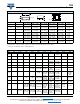
TR3 www.vishay.com Vishay Sprague RATINGS AND CASE CODES μF 10 15 22 33 47 68 100 150 220 4V 6.3 V 10 V 16 V 20 V 25 V A (2.00, 1.80, A (1.70), B (1.00, 0.50), B (1.30, 1.10, 0.90, 0.45), A (2.00, 1.50), 1.00, 0.90), B (0.80, 0.50), C (0.70, 0.50, C (0.60, 0.50, B (1.50) B (1.00, 0.80, C (0.60, 0.50, 0.475, 0.45, 0.45, 0.30), 0.75) 0.45) 0.40) D (0.40, 0.30) 35 V 50 V C (1.20, 0.45), D (0.40, 0.30, D (0.70, 0.55, 0.45), 0.26, 0.25, E (0.70, 0.55, 0.20, 0.135, 0.50, 0.40, 0.125), 0.
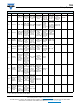
TR3 www.vishay.com Vishay Sprague RATINGS AND CASE CODES μF 330 470 680 1000 4V 6.3 V 10 V D (0.15, 0.125, 0.10, D (0.15, 0.06, 0.05, D (0.10, 0.45, 0.45, 0.35), 0.125, 0.10), E (0.10, 0.06), 0.035, 0.15) E (0.15, 0.10, W (0.10, 0.06, 0.05), 0.04) W (0.10, 0.06, 0.04) D (0.20, 0.15, D (0.125, 0.125, 0.10), 0.10, 0.06, E (0.10, E (0.20, 0.15, 0.10, 0.075), 0.045, 0.035) 0.065, 0.06, W (0.10, 0.06, E (0.10, 0.05), 0.05) 0.045, 0.035) W (0.10, 0.06, 0.05) D (0.10, 0.06), E (0.10) E (0.10, 0.04) E (0.
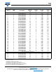
TR3 www.vishay.com Vishay Sprague STANDARD RATINGS CAPACITANCE (μF) CASE CODE 15 22 33 33 47 47 47 68 68 100 100 100 150 150 150 150 150 220 220 220 220 220 220 220 220 330 330 330 330 470 470 470 470 470 470 470 470 680 680 680 680 1000 A A A B A A B B C A B C B B B C D B B B B C D D D D D D D D D D D D E E E D D E E E 3.3 6.8 10 10 10 15 15 A A A A B A A PART NUMBER MAX. DCL AT +25 °C (μA) 4 VDC AT +85 °C; 2.7 VDC AT +125 °C TR3A156(1)004(2)1500 0.6 TR3A226(1)004(2)1500 0.
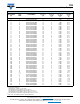
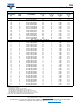
TR3 www.vishay.com Vishay Sprague STANDARD RATINGS CAPACITANCE (μF) CASE CODE 22 22 22 22 22 22 33 33 33 33 33 33 33 47 47 47 47 47 47 47 68 68 68 68 68 68 68 68 68 68 100 100 100 100 100 100 100 100 100 100 100 100 100 150 150 150 150 150 150 150 150 A A A A B C A A A B B B B A B B B B C C B B B B B C C C D D B B B B C C C C C D D V (1) V (1) C C D D D D D E PART NUMBER MAX. DCL AT +25 °C (μA) 6.3 VDC AT +85 °C; 4 VDC AT +125 °C TR3A226(1)6R3(2)3000 1.4 TR3A226(1)6R3(2)2000 1.
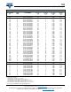
TR3 www.vishay.com Vishay Sprague STANDARD RATINGS CAPACITANCE (μF) CASE CODE 220 220 220 220 220 220 220 220 220 220 330 330 330 330 330 330 330 330 330 330 330 330 330 470 470 470 470 470 470 470 470 470 470 470 680 1000 1000 1000 1000 C C C D D D E E V (1) V (1) D D D D D D D E E E W W W D D D D E E E E W W W E E E E W 2.2 2.2 2.2 4.7 4.7 4.7 4.7 4.7 6.8 6.8 6.8 A A A A A A A B A A B PART NUMBER MAX. DCL AT +25 °C (μA) 6.3 VDC AT +85 °C; 4 VDC AT +125 °C TR3C227(1)6R3(2)0300 13.
TR3 www.vishay.
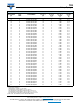
TR3 www.vishay.com Vishay Sprague STANDARD RATINGS CAPACITANCE (μF) CASE CODE 68 68 68 68 68 68 68 68 68 68 68 68 68 68 68 68 68 68 100 100 100 100 100 100 100 100 100 100 100 100 100 100 100 100 150 150 150 150 150 150 150 150 220 220 220 220 220 220 220 220 220 220 220 B B B B C C C C D D D D E V (1) V (1) V (1) V (1) V (1) B C C C D D D D D D E E E V (1) V (1) V (1) C D D D D D E E D D D D E E E E E V (1) V (1) PART NUMBER MAX.
TR3 www.vishay.com Vishay Sprague STANDARD RATINGS CAPACITANCE (μF) CASE CODE 330 330 330 330 330 330 330 330 470 470 470 470 470 470 470 D D D E E W W W E E E E W W W 1.0 2.2 2.2 2.2 3.3 3.3 3.3 4.7 4.7 4.7 4.7 4.7 4.7 6.8 6.8 6.8 6.8 10 10 10 10 10 10 15 15 15 22 22 22 22 22 22 22 A A A A A A B A A A A B B A A B B A B B C C C B B C B B B B C C D PART NUMBER MAX. DCL AT +25 °C (μA) 10 VDC AT +85 °C; 7 VDC AT +125 °C TR3D337(1)010(4)0150 33.0 TR3D337(1)010(4)0125 33.0 TR3D337(1)010(4)0100 33.
TR3 www.vishay.com Vishay Sprague STANDARD RATINGS CAPACITANCE (μF) CASE CODE 33 33 33 33 33 33 33 33 47 47 47 47 47 47 47 47 47 68 68 68 100 100 100 100 100 100 100 100 100 150 150 150 150 150 150 150 150 150 150 150 150 150 150 220 220 220 B B B C C D D D C C C D D D D D D D D D D D D D E E E V (1) V (1) D D D D D D D E E E E E W W E E E 1.0 1.0 1.5 2.2 2.2 3.3 3.3 A A A A A A B PART NUMBER MAX. DCL AT +25 °C (μA) 16 VDC AT +85 °C; 10 VDC AT +125 °C TR3B336(1)016(2)0700 5.
TR3 www.vishay.com Vishay Sprague STANDARD RATINGS CAPACITANCE (μF) CASE CODE 4.7 4.7 4.7 4.7 6.8 6.8 6.8 6.8 6.8 10 10 10 10 10 10 10 15 15 15 22 22 22 22 22 22 22 22 33 33 33 33 33 33 47 47 47 47 47 47 68 68 68 68 68 68 68 68 A A B B A A A B B B B C C C C C B B C B B B C C D D D C C C D D D D D D D E E D D D D E E E E PART NUMBER MAX. DCL AT +25 °C (μA) 20 VDC AT +85 °C; 13 VDC AT +125 °C TR3A475(1)020(2)3500 0.9 TR3A475(1)020(2)1800 0.9 TR3B475(1)020(2)1000 0.9 TR3B475(1)020(2)0750 0.
TR3 www.vishay.com Vishay Sprague STANDARD RATINGS CAPACITANCE (μF) CASE CODE 100 100 100 100 100 100 100 100 100 100 100 100 150 150 150 150 D D D D D E E E W W W W W W W W 0.47 0.68 1.0 1.5 1.5 1.5 2.2 2.2 2.2 2.2 2.2 3.3 3.3 3.3 3.3 3.3 4.7 4.7 4.7 4.7 4.7 4.7 4.7 4.7 6.8 6.8 6.8 6.8 6.8 6.8 6.8 6.8 A A A A A B A B B B B A A B B B A A B B B B C C B B B B B B C C PART NUMBER MAX. DCL AT +25 °C (μA) 20 VDC AT +85 °C; 13 VDC AT +125 °C TR3D107(1)020(4)0200 20.0 TR3D107(1)020(4)0150 20.
TR3 www.vishay.com Vishay Sprague STANDARD RATINGS CAPACITANCE (μF) CASE CODE 10 10 10 10 10 10 10 10 10 10 15 15 15 15 15 15 15 15 15 22 22 22 22 22 22 22 22 22 22 22 22 22 22 33 33 33 33 33 33 33 47 47 47 47 47 47 B B B B C C C C D D B B B C C D D D D C C C C C C C D D E E V (1) V (1) V (1) D D D D E E E D D D D D D PART NUMBER MAX. DCL AT +25 °C (μA) 25 VDC AT +85 °C; 17 VDC AT +125 °C TR3B106(1)025(2)1300 2.5 TR3B106(1)025(2)1100 2.5 TR3B106(1)025(2)0900 2.5 TR3B106(1)025(2)0450 2.
TR3 www.vishay.com Vishay Sprague STANDARD RATINGS CAPACITANCE (μF) CASE CODE 47 47 47 47 47 68 68 100 100 100 E E E E E E E W W W 0.22 0.33 0.47 0.47 0.68 0.68 1.0 1.0 1.0 1.0 1.5 1.5 1.5 1.5 2.2 2.2 2.2 2.2 2.2 3.3 3.3 3.3 3.3 3.3 4.7 4.7 4.7 4.7 4.7 4.7 4.7 6.8 6.8 6.8 6.8 6.8 6.8 A A A B A A A A A B B B C C B B B C C B B C C C B B B C C C D C C D D D E PART NUMBER MAX. DCL AT +25 °C (μA) 25 VDC AT +85 °C; 17 VDC AT +125 °C TR3E476(1)025(4)0300 11.8 TR3E476(1)025(4)0200 11.
TR3 www.vishay.com Vishay Sprague STANDARD RATINGS CAPACITANCE (μF) CASE CODE 10 10 10 10 10 10 10 10 10 10 10 15 15 15 15 15 15 15 15 15 15 15 15 22 22 22 22 22 22 22 22 22 33 33 33 33 47 47 C C D D D D D D D E E C C D D D D D D E E E E D D D D D E E E E D D E E E E 0.15 0.22 0.33 0.47 0.47 1.0 1.0 1.0 1.5 1.5 2.2 2.2 2.2 A A A B C B B C B C B C D PART NUMBER MAX. DCL AT +25 °C (μA) 35 VDC AT +85 °C; 23 VDC AT +125 °C TR3C106(1)035(2)1200 3.5 TR3C106(1)035(2)0450 3.5 TR3D106(1)035(4)0400 3.
TR3 www.vishay.com Vishay Sprague STANDARD RATINGS CAPACITANCE (μF) CASE CODE 3.3 3.3 4.7 4.7 4.7 4.7 4.7 4.7 4.7 4.7 4.7 6.8 6.8 6.8 6.8 6.8 6.8 10 10 10 10 10 10 10 10 15 15 15 15 C D C C C D D D D E E D D D D E E D D D E E E E E E E E E 3.3 3.3 4.7 4.7 10 D D D D E 1.0 1.0 1.5 1.5 1.5 1.5 2.2 3.3 3.3 3.3 4.7 D D B C D D D D D D E PART NUMBER MAX. DCL AT +25 °C (μA) 50 VDC AT +85 °C; 33 VDC AT +125 °C TR3C335(1)050(2)1500 1.7 TR3D335(1)050(4)0800 1.7 TR3C475(1)050(2)1000 2.
TR3 www.vishay.com Vishay Sprague TYPICAL CURVES AT +25 °C, IMPEDANCE AND ESR VS. FREQUENCY “D” Case “D” Case 1.00 1.00 68 µF, 20 VDC 0.10 IMPEDANCE ESR ESR/Z, Ω ESR/Z, Ω IMPEDANCE ESR 0.10 220 µF, 10 VDC 330 µF, 6.3 VDC 470 µF, 4 VDC 0.01 0.1 0.01 1.0 10.0 100.0 1000.0 FREQUENCY kHz 0.1 1.0 10.0 100.0 1000.0 FREQUENCY kHz POWER DISSIPATION CASE CODE A B C D E V W MAXIMUM PERMISSIBLE POWER DISSIPATION AT +25 °C (W) IN FREE AIR 0.075 0.085 0.110 0.150 0.165 0.125 0.
Molded Guide www.vishay.com Vishay Sprague Guide for Molded Tantalum Capacitors INTRODUCTION Tantalum electrolytic capacitors are the preferred choice in applications where volumetric efficiency, stable electrical parameters, high reliability, and long service life are primary considerations. The stability and resistance to elevated temperatures of the tantalum / tantalum oxide / manganese dioxide system make solid tantalum capacitors an appropriate choice for today's surface mount assembly technology.
Molded Guide www.vishay.com Vishay Sprague SOLID ELECTROLYTE TANTALUM CAPACITORS Solid electrolyte capacitors contain manganese dioxide, which is formed on the tantalum pentoxide dielectric layer by impregnating the pellet with a solution of manganous nitrate. The pellet is then heated in an oven, and the manganous nitrate is converted to manganese dioxide.
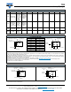
Molded Guide www.vishay.com Vishay Sprague COMMERCIAL PRODUCTS SOLID TANTALUM CAPACITORS - MOLDED CASE SERIES 793DX-CTC3CTC4 293D 593D TR3 TP3 TL3 High performance, automotive grade Very low DCL PRODUCT IMAGE Surface mount TANTAMOUNT™, molded case TYPE FEATURES Standard industrial grade CECC approved Low ESR TEMPERATURE RANGE CAPACITANCE RANGE VOLTAGE RANGE CAPACITANCE TOLERANCE -55 °C to +125 °C 0.1 μF to 1000 μF 0.1 μF to 100 μF 1 μF to 470 μF 0.47 μF to 1000 μF 0.1 μF to 470 μF 0.
Molded Guide www.vishay.com Vishay Sprague HIGH RELIABILITY PRODUCTS SOLID TANTALUM CAPACITORS - MOLDED CASE SERIES TM3 T83 CWR11 TANTAMOUNT™, molded case, hi-rel. TANTAMOUNT™, molded case, hi-rel.
Molded Guide www.vishay.com Vishay Sprague PLASTIC TAPE AND REEL PACKAGING in inches [millimeters] 0.157 ± 0.004 [4.0 ± 0.10] Tape thickness Deformation between embossments 0.014 [0.35] MAX. 0.059 + 0.004 - 0.0 [1.5 + 0.10 - 0.0] Top cover tape B1 MAX. (Note 6) Center lines of cavity 0.069 ± 0.004 [1.75 ± 0.10] Embossment 0.030 [0.75] MIN. (Note 3) B0 Top cover tape For tape feeder reference only including draft. Concentric around B0 (Note 5) 0.079 ± 0.002 [2.0 ± 0.05] A0 K0 0.004 [0.1] MAX.
Molded Guide www.vishay.com Vishay Sprague RECOMMENDED REFLOW PROFILES Capacitors should withstand reflow profile as per J-STD-020 standard, three cycles. TEMPERATURE (°C) Tp TL Ts max. TC - 5 °C tp Max. ramp-up rate = 3 °C/s Max. ramp-down rate = 6 °C/s tL Preheat area Ts min. ts 25 Time 25 °C to peak TIME (s) PROFILE FEATURE Preheat / soak Temperature min. (Ts min.) Temperature max. (Ts max.) Time (ts) from (Ts min. to Ts max.
Molded Guide www.vishay.com Vishay Sprague GUIDE TO APPLICATION 1. AC Ripple Current: the maximum allowable ripple current shall be determined from the formula: be established when calculating permissible operating levels. (Power dissipation calculated using +25 °C temperature rise). P -----------R ESR 6. power dissipation in W at +25 °C as given in the tables in the product datasheets (Power Dissipation).
Typical Performance Characteristics www.vishay.com Vishay Sprague Molded Chip Tantalum Capacitors CAPACITOR ELECTRICAL PERFORMANCE CHARACTERISTICS ITEM PERFORMANCE CHARACTERISTICS Category temperature range -55 °C to +85 °C (to +125 °C with voltage derating) Capacitance tolerance ± 20 %, ± 10 %. Tested via bridge method, at +25 °C, 120 Hz Dissipation factor Limit per Standard Ratings table. Tested via bridge method, at 25 °C, 120 Hz ESR Limit per Standard Ratings table.
Typical Performance Characteristics www.vishay.com Vishay Sprague TYPICAL LEAKAGE CURRENT TEMPERATURE FACTOR 100 +175 °C +150 °C +125 °C 10 Leakage Current Factor +85 °C +55 °C 1 +25 °C 0 °C 0.1 -55 °C 0.01 0.
Typical Performance Characteristics www.vishay.com Vishay Sprague MECHANICAL PERFORMANCE CHARACTERISTICS TEST CONDITION CONDITION POST TEST PERFORMANCE Terminal strength / shear force test Apply a pressure load of 17.7 N for 60 s horizontally to the center of capacitor side body. Capacitance change Dissipation factor Leakage current Within ± 10 % of initial value Initial specified limit Initial specified limit There shall be no mechanical or visual damage to capacitors post-conditioning.
Legal Disclaimer Notice www.vishay.com Vishay Disclaimer ALL PRODUCT, PRODUCT SPECIFICATIONS AND DATA ARE SUBJECT TO CHANGE WITHOUT NOTICE TO IMPROVE RELIABILITY, FUNCTION OR DESIGN OR OTHERWISE. Vishay Intertechnology, Inc., its affiliates, agents, and employees, and all persons acting on its or their behalf (collectively, “Vishay”), disclaim any and all liability for any errors, inaccuracies or incompleteness contained in any datasheet or in any other disclosure relating to any product.