
Instruction Manual


www.vishay.com
4
Document Number 82177
Rev. 3, 23-Jun-03
VISHAY
TSOP62..
Vishay Semiconductors
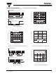
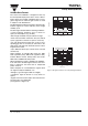
Figure 7. Sensitivity vs. Supply Voltage Disturbances
Figure 8. Sensitivity vs. Electric Field Disturbances
Figure 9. Max. Envelope Duty Cycle vs. Burstlength
0.0
0.5
1.0
1.5
2.0
0.1 1.0 10.0 100.0 1000.0
DV
sRMS
– AC Voltage on DC Supply Voltage (mV)
16912
f = f
o
f = 10 kHz
E – Threshold Irradiance ( mW/m )
e min
2
f = 1 kHz
f = 100 Hz
E – Threshold Irradiance ( mW/m )
0.0 0.4 0.8 1.2 1.6
0.0
0.4
0.8
1.2
2.0
E – Field Strength of Disturbance ( kV/m )
2.0
94 8147
1.6
e min
2
f(E) = f
0
0.0
0.1
0.2
0.3
0.4
0.5
0.6
0.7
0.8
0 20 40 60 80 100 120
Burst Length ( number of cycles / burst )
16913
f = 38 kHz, E
e
= 2 mW/m
2
Max. Envelope Duty Cycle
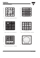
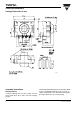
Figure 10. Sensitivity vs. Ambient Temperature
Figure 11. Relative Spectral Sensitivity vs. Wavelength
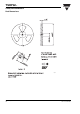
Figure 12. Directivity
0.0
0.1
0.2
0.3
0.4
0.5
0.6
–30–150 153045607590
T
amb
– Ambient Temperature ( qC )
16918
Sensitivity in dark ambient
E – Threshold Irradiance ( mW/m )
e min
2
0.0
0.2
0.4
0.6
0.8
1.0
1.2
750 850 950 1050 1150
l – Wavelength ( nm )
16919
S ( ) – Relative Spectral Sensitivityl
rel
16801
0.4 0.2 0 0.2 0.4
0.6
0.6
0.9
0°
30°
10° 20°
40°
50°
60°
70°
80°
1.0
0.8
0.7
d
rel
- Relative Transmission Distance