
Datasheet


VCNL4010
www.vishay.com
Vishay Semiconductors
Rev. 1.6, 20-Mar-18
11
Document Number: 83462
For technical questions, contact: sensorstechsupport@vishay.com
THIS DOCUMENT IS SUBJECT TO CHANGE WITHOUT NOTICE. THE PRODUCTS DESCRIBED HEREIN AND THIS DOCUMENT
ARE SUBJECT TO SPECIFIC DISCLAIMERS, SET FORTH AT www.vishay.com/doc?91000
Register #15 Proximity Modulator Timing Adjustment
Register address = 8Fh.
Note
• The settings for best performance will be provided by Vishay. With first samples this is evaluated to:
delay time = 0; dead time = 1 and prox. frequency = 0. With that register#15 should be programmed with 1 (= default value).
Register #16 Ambient IR Light Level Register
Register address = 90h.
This register is not intended to be used by customer.
3. IMPORTANT APPLICATION HINTS AND EXAMPLES
3.1 Receiver standby mode
In standby mode the receiver has the lowest current consumption of about 1.5 μA. In this mode only the I
2
C interface is active.
This is always valid, when there are no measurement demands for proximity and ambient light executed. Also the current sink
for the IR-LED is inactive, so there is no need for changing register #3 (IR LED current).
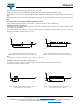
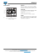
3.2 Data Read
In order to get a certain register value, the register has to be addressed without data like shown in the following scheme. After
this register addressing, the data from the addressed register is written after a subsequent read command.
Fig. 14 - Send Byte/Receive Byte Protocol
The stop condition between these write and read sequences is not mandatory. It works also with a repeated start condition.
Note
• For reading out 2 (or more) subsequent registers like the result registers, it is not necessary to address each of the registers separately. After
one read command the internal register counter is increased automatically and any subsequent read command is accessing the next
register.
TABLE 16 - PROXIMITY MODULATOR TIMING ADJUSTMENT #15
Bit 7Bit 6Bit 5Bit 4Bit 3Bit 2Bit 1Bit 0
Modulation delay time Proximity frequency Modulation dead time
Description
Modulation delay time
R/W bits. Setting a delay time between IR LED signal and IR input signal evaluation.
This function is for compensation of delays from IR LED and IR photo diode. Also in respect to the
possibility for setting different proximity signal frequency. Correct adjustment is optimizing measurement
signal level. ( DEFAULT = 0)
Proximity frequency
R/W bits. Setting the proximity IR test signal frequency
The proximity measurement is using a square IR signal as measurement signal. Four different values are
possible:
00 = 390.625 kHz (DEFAULT)
01 = 781.25 kHz
10 = 1.5625 MHz
11 = 3.125 MHz
Modulation dead time
R/W bits. Setting a dead time in evaluation of IR signal at the slopes of the IR signal. ( DEFAULT = 1)
This function is for reducing of possible disturbance effects.
This function is reducing signal level and should be used carefully.
S
Slave address
Rd
Receive byte Read data from VCNL4010
ARegister address
AWr P
S
Slave address
PA
A
Data byte
S = start condition
P = stop condition
A = acknowledge
Host action
VCNL4010 response