
Datasheet


VDRS Series
www.vishay.com
Vishay BCcomponents
Revision: 19-Jun-15
1
Document Number: 29081
For technical questions, contact: nlr@vishay.com
THIS DOCUMENT IS SUBJECT TO CHANGE WITHOUT NOTICE. THE PRODUCTS DESCRIBED HEREIN AND THIS DOCUMENT
ARE SUBJECT TO SPECIFIC DISCLAIMERS, SET FORTH AT www.vishay.com/doc?91000
VDR Metal Oxide Varistors Standard
ORDERING INFORMATION
The varistors are available in a number of packaging
options:
•Bulk
• On tape and reel
• On tape in ammopack
The basic ordering code for each option is given in tables
titled Varistors on Tape on Reel, Varistors on Tape in
Ammopack and Varistors in Bulk. To complete the catalog
number and to determine the required operating
parameters, see Electrical Data and Ordering Information
table.
Note
• Special lead-configuration as inside or outside crimped leads on
request.
FEATURES
•Low high purity zinc oxide disc
• Halogen free insulating epoxy coating
• Zinc oxide disc, HF epoxy coated
• Straight leads and kinked leads
• Straight leads with flange (VDRS05 and
VDRS07 only)
• Certified according to UL 1449 edition 3,
VDE/IEC 61051-1/2 and CSA
• Material categorization: for definitions of compliance
please see www.vishay.com/doc?99912
APPLICATION
• Overvoltage and transient voltage protection
DESCRIPTION
The varistors consist of a disc of low- ZnO ceramic material
with two solid copper leads (S20 types only) or copper clad
steel wire. The wires have a matte tin plating. They are
coated with a layer of ocher colored halogen-free epoxy,
which provides electrical, mechanical and climatic
protection. The encapsulation is resistant to all cleaning
solvents in accordance with IEC 60068-2-45.
MOUNTING
The varistors are suitable for processing on automatic
insertion and cutting and bending equipment.
Varistors with flanged leads provide better positioning on
printed-circuit boards (PCB) and more accurate control over
component height. This is important for hand mounting and
automatic insertion techniques; see outlines of flanged
leads drawing.
Typical soldering
235 °C, duration: 5 s (Pb-bearing)
245 °C, duration: 5 s (lead (Pb)-free)
Resistance to soldering heat
260 °C, duration: 10 s max.
MARKING
The varistors are marked with the following information:
• Maximum continuous RMS voltage
• Series number (592, 593, 594, 595 or 596)
• Safety marks on VDRS10-14-20 types
• Manufacturers logo
• Date of manufacture (YYWW)
INFLAMMABILITY
The varistors are passive non-flammable.
The encapsulation is made of flammable resistant epoxy in
accordance with UL 94 V-0.
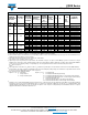
QUICK REFERENCE DATA
PARAMETER VALUE UNIT
Maximum continuous voltage in
operating temperature range:
RMS 14 to 680 V
DC 18 to 895 V
Maximum non-repetitive transient
current I
NRP
(8 x 20 μs)
100 to 6500 A
Maximum energy
(10/1000 μs)
0.5 to 496 J
Detailed specification
Based on
IEC 61051-1
IEC 61051-2
IEC 61051-2-2
Storage temperature -40 to +125 °C
Operating temperature -40 to +85 °C