
Datasheet


VLMR51Z1AA, VLMK51Z1AA, VLMY51Z1AA
www.vishay.com
Vishay Semiconductors
Rev. 1.4, 03-Sep-13
1
Document Number: 83419
For technical questions, contact: LED@vishay.com
THIS DOCUMENT IS SUBJECT TO CHANGE WITHOUT NOTICE. THE PRODUCTS DESCRIBED HEREIN AND THIS DOCUMENT
ARE SUBJECT TO SPECIFIC DISCLAIMERS, SET FORTH AT www.vishay.com/doc?91000
Power SMD LED PLCC-2 Plus
DESCRIPTION
The VLMR51.., VLMK51.., and VLMY51.. LED series in
PLCC2 plus package are an advanced product in terms of
high luminous flux and low thermal resistance.
In combination with the small package outline (3.5 mm x
3.5 mm x 1.2 mm) the PLCC2 plus is an ideal choice for
backlighting, signage, exterior and interior automotive
lighting as well as decorative lighting.
PRODUCT GROUP AND PACKAGE DATA
• Product group: LED
• Package: SMD PLCC-2 plus
• Product series: power
• Angle of half intensity: ± 60°
FEATURES
• High efficient AlInGaP technology
• Compact package outline 3.5 mm x 3.5 mm x
1.2 mm
• Angle of half intensity ϕ = ± 60°
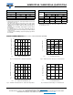
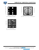
• Luminous intensity and color categorized per
packing unit
• Luminous intensity ratio per packing unit
φ
min.
/φ
max.
< 1.6
• ESD-withstand voltage: Up to 2 kV (HBM)
according to JESD22-A114-B
• Preconditioning according to JEDEC
®
level 2a
• Compatible with IR-reflow soldering profiles
according to J-STD-020
• AEC-Q101 qualified
• Material categorization: For definitions of compliance
please see www.vishay.com/doc?99912
APPLICATIONS
• Interior and exterior automotive lighting: Dashboard,
brake lights, turn lights, backlighting
• Signal and symbol luminaire
• Decorative lighting
• Architectural lighting
• Backlighting: LCDs, switches, keys, illuminated
advertising
•Marker lights
• Traffic lights
22068
PARTS TABLE
PART COLOR
LUMINOUS
INTENSITY
(mcd)
at I
F
(mA)
WAVELENGTH
(nm)
at I
F
(mA)
FORWARD
VOLTAGE
(V)
at I
F
(mA)
TECHNOLOGY
MIN. TYP. MAX. MIN. TYP. MAX. MIN. TYP. MAX.
VLMR51Z1AA-GS08 Red 4500 7100 9000 140 620 - 630 140 1.9 2.2 2.65 140 AlInGaP on Si
VLMK51Z1AA-GS08 Amber 4500 7100 9000 140 610 - 621 140 1.9 2.2 2.65 140 AlInGaP on Si
VLMY51Z1AA-GS08 Yellow 4500 7100 9000 140 585 - 594 140 1.9 2.2 2.65 140 AlInGaP on Si
ABSOLUTE MAXIMUM RATINGS (T
amb
= 25 °C, unless otherwise specified)
VLMR51.., VLMK51.., VLMY51..
PARAMETER TEST CONDITION SYMBOL VALUE UNIT
Reverse voltage I
R
= 10 μA V
R
12 V
DC forward current I
F
200 mA
Surge forward current t
p
≤ 10 μs I
FSM
1000 mA
Power dissipation P
V
530 mW
Junction temperature T
j
125 °C
Operating temperature range T
amb
- 40 to + 110 °C
Storage temperature range T
stg
- 40 to + 110 °C
Thermal resistance junction/solder point R
thJS
50 K/W
Thermal resistance junction/ambient Mounted on PCB, total Cu area > 900 mm
2
R
thJA
100 K/W