
Datasheet


VLMS334.., VLMR334.., VLMK334.., VLMY334..
www.vishay.com
Vishay Semiconductors
Rev. 1.1, 07-Mar-17
1
Document Number: 84213
For technical questions, contact: LED@vishay.com
THIS DOCUMENT IS SUBJECT TO CHANGE WITHOUT NOTICE. THE PRODUCTS DESCRIBED HEREIN AND THIS DOCUMENT
ARE SUBJECT TO SPECIFIC DISCLAIMERS, SET FORTH AT www.vishay.com/doc?91000
Power SMD LED PLCC-2
DESCRIPTION
The VLM.334.. series is an advanced modification of the
Vishay VLM.31.. series. It is designed to incorporate larger
chips, therefore, capable of withstanding a 70 mA drive
current.
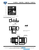
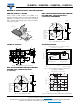
The package of the VLM.334.. is the PLCC-2.
It consists of a lead frame which is embedded in a white
thermoplast. The reflector inside this package is filled up
with clear epoxy.
PRODUCT GROUP AND PACKAGE DATA
• Product group: LED
• Package: SMD PLCC-2
• Product series: power
• Angle of half intensity: ± 60°
FEATURES
• Utilizing latest advanced AlInGaP technology
• Available in 8 mm tape
• Luminous intensity and color categorized per
packing unit
• Luminous intensity ratio per packing unit
I
Vmax.
/I
Vmin.
≤ 1.6
• Thermal resistance R = 300 K/W
• ESD-withstand voltage: Up to 2 kV according
to JESD22-A114-B
• Preconditioning according to JEDEC
®
level 2a
• Compatible with reflow, vapor phase and
wave solder processes according to
CECC 00802 and J-STD-020
• AEC-Q101 qualified
• Material categorization: for definitions of compliance
please see www.vishay.com/doc?99912
APPLICATIONS
• Traffic signals and signs
• Interior and exterior lighting
• Dashboard illumination
• Indicator and backlighting purposes for audio, video,
LCDs switches, symbols, illuminated advertising etc.
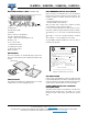
Note
(1)
Driving the LED in reverse direction is suitable for a short term application
19225
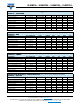
PARTS TABLE
PART COLOR
LUMINOUS
INTENSITY
(mcd)
at
I
F
(mA)
WAVELENGTH
(nm)
at
I
F
(mA)
FORWARD
VOLTAGE
(V)
at
I
F
(mA)
TECHNOLOGY
MIN. TYP. MAX. MIN. TYP. MAX. MIN. TYP. MAX.
VLMS334AABB-GS08 Super red 1120 1600 2800 50 626 630 639 50 1.9 2.2 2.8 50 AlInGaP on Si
VLMS334AABB-GS18 Super red 1120 1600 2800 50 626 630 639 50 1.9 2.2 2.8 50 AlInGaP on Si
VLMR334BACB-GS08 Red 1800 2200 4500 50 619 625 631 50 1.9 2.2 2.8 50 AlInGaP on Si
VLMR334BACB-GS18 Red 1800 2200 4500 50 619 625 631 50 1.9 2.2 2.8 50 AlInGaP on Si
VLMK334BACB-GS08 Amber 1800 2800 4500 50 611 616 622 50 1.9 2.25 2.8 50 AlInGaP on Si
VLMK334BACB-GS18 Amber 1800 2800 4500 50 611 616 622 50 1.9 2.25 2.8 50 AlInGaP on Si
VLMY334BACB-GS08 Yellow 1800 2300 4500 50 583 589 594 50 1.9 2.3 2.8 50 AlInGaP on Si
VLMY334BACB-GS18 Yellow 1800 2300 4500 50 583 589 594 50 1.9 2.3 2.8 50 AlInGaP on Si
ABSOLUTE MAXIMUM RATINGS (T
amb
= 25 °C, unless otherwise specified)
VLMS334..., VLMR334..., VLMK334..., VLMY334...
PARAMETER TEST CONDITION SYMBOL VALUE UNIT
Reverse voltage
(1)
Short term application only V
R
5V
DC forward current T
amb
≤ 65 °C (300 K/W) I
F
70 mA
Surge forward current t
p
≤ 10 μs I
FSM
0.1 A
Power dissipation P
V
200 mW
Junction temperature T
j
125 °C
Operating temperature range T
amb
-40 to +100 °C
Storage temperature range T
stg
-40 to +100 °C
Thermal resistance junction-to-ambient Mounted on PC board (pad size > 16 mm
2
)R
thJA
300 K/W