
Datasheet

VLMW11..
www.vishay.com
Vishay Semiconductors
Rev. 1.5, 27-Sep-13
1
Document Number: 81602
For technical questions, contact: LED@vishay.com
THIS DOCUMENT IS SUBJECT TO CHANGE WITHOUT NOTICE. THE PRODUCTS DESCRIBED HEREIN AND THIS DOCUMENT
ARE SUBJECT TO SPECIFIC DISCLAIMERS, SET FORTH AT www.vishay.com/doc?91000
Ultrabright 0603 SMD LED
DESCRIPTION
The new 0603 LED series have been designed in the
smallest SMD package. This innovative 0603 LED
technology opens the way to
• smaller products of higher performance
• more design in flexibility
• enhanced applications
The 0603 LED is an obvious solution for small-scale, high
power products that are expected to work reliability in an
arduous environment.
The reflector inside this package is filled with a mixture of
epoxy and yellow converter.
This yellow converter converts the blue emission partially to
yellow, which mixes the remaining blue to give white.
PRODUCT GROUP AND PACKAGE DATA
• Product group: LED
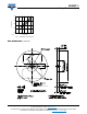
• Package: SMD 0603
• Product series: standard
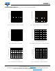
• Angle of half intensity: ± 80°
FEATURES
• High efficient InGaN technology
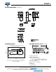
• Smallest SMD package 0603 with exceptional
brightness 1.6 mm x 0.8 mm x 0.6 mm (L x W x H)
• High reliability lead frame based
• Temperature range -40 °C to +100 °C
• Chromaticity coordinate categorized according to
CIE1931 per packing unit
• Typical color temperature 5500 K
• EIA and ICE standard package
• Compatible to IR reflow soldering
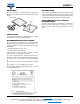
• Available in 8 mm tape reel
• Preconditioning according to JEDEC
®
level 2
• ESD-withstand voltage: Up to 1 kV according to
JESD22-A114-B
• AEC-Q101 qualified
• Material categorization: For definitions of compliance
please see www.vishay.com/doc?99912
APPLICATIONS
• Automotive: Backlighting in dashboards, switches, and
keypads
• Telecommunication: Indicator and backlighting in
telephone and fax
• Backlighting for audio, and video equipment
• Backlighting in office equipment
• Indoor and outdoor message boards
• Flat backlight for LCDs, switches, and symbols
Note
(1)
Driving the LED in reverse direction is suitable for short term application
18562
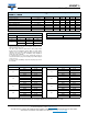
PARTS TABLE
PART COLOR
LUMINOUS
INTENSITY
(mcd)
at I
F
(mA)
COORDINATE
(x, y)
at I
F
(mA)
FORWARD
VOLTAGE
(V)
at I
F
(mA)
TECHNOLOGY
MIN. TYP. MAX. MIN. TYP. MAX. MIN. TYP. MAX.
VLMW11R2S2-5K8L-08 White 140 - 280 10 -
0.33,
0.33
- 10 2.9 - 4.0 20
InGaN/yellow
converter
ABSOLUTE MAXIMUM RATINGS (T
amb
= 25 °C, unless otherwise specified)
VLMW11..
PARAMETER TEST CONDITION SYMBOL VALUE UNIT
Reverse voltage
(1)
I
R
max. = 10 μA V
R
5V
DC forward current T
amb
60 °C I
F
20 mA
Surge forward current t
p
10 μs I
FSM
0.1 A
Power dissipation P
V
80 mW
Junction temperature T
j
110 °C
Storage temperature range T
stg
-40 to +100 °C
Operating temperature range T
amb
-40 to +100 °C
Thermal resistance junction/ambient mounted on PC board (pad size > 16 mm
2
)R
thJA
480 K/W