
Datasheet


www.vishay.com For technical questions, contact: ind-modules@vishay.com
Document Number: 93586
2 Revision: 29-Sep-08
KBPC8 Series
Vishay High Power Products
Single Phase Rectifier
Bridge, 8 A
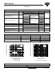
Fig. 1 - Current Ratings Fig. 2 - Non-Repetitive Surge Ratings
FORWARD CONDUCTION
PARAMETER SYMBOL TEST CONDITIONS VALUES UNITS
Maximum DC output current I
O
T
C
= 50 °C, resistive or inductive load 8.0
A
T
C
= 50 °C, capacitive load 6.4
Maximum peak one cycle,
non-repetitive surge current
I
FSM
t = 10 ms, 20 ms
Following any rated load
condition and with rated
V
RRM
reapllied
125
t = 8.3 ms, 16.7 ms 137
Maximum I
2
t capability for fusing I
2
t
t = 10 ms
Initial T
J
= T
J
maximum
100 % V
RRM
reapplied
78
A
2
s
t = 8.3 ms 71
t = 10 ms 110
t = 8.3 ms 1000
Maximum I
2
√t capability for fusing I
2
√t t = 0.1 to 10 ms, no voltage reapplied 1105 A
2
√s
Maximum peak forward voltage per diode V
FM
I
FM
= 3.0 A, T
J
= 25 °C 1.0 V
Typical peak reverse leakage per diode I
RM
T
J
= 25 °C, 100 % V
RRM
10
mA
T
J
= 150 °C, 100 % V
RRM
100
Operating frequency range f 400 to 1000 Hz
Maximum repetitive peak reverse
voltage range
V
RRM
50 to 1000 V
THERMAL AND MECHANICAL SPECIFICATIONS
PARAMETER SYMBOL VALUES UNITS
Operating and storage temperature range T
J
, T
Stg
- 55 to 150 °C
Thermal resistance, junction to case R
thJC
6K/W
Approximate weight
6g
0.21 oz.
10
9
8
7
6
5
4
3
2
1
0
20 40 60 80 100 120 140 160
0
Average Output Current (A)
Maximum Allowable Ambient
Temperature (°C)
KBPC8...
Resistive load
Capacitive load
140
130
120
110
100
90
80
70
60
50
40
30
20
10
0
0.01
0.1
1.0
10
KBPC8
50 Hz
Maximum Peak Surge Current (A)
Pulse Train Duration (s)
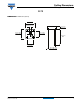
LINKS TO RELATED DOCUMENTS
Dimensions http://www.vishay.com/doc?95250