
Datasheet

VS-MBRS190-M3, VS-MBRS1100-M3
www.vishay.com
Vishay Semiconductors
Revision: 23-Apr-2019
1
Document Number: 95744
For technical questions within your region: DiodesAmericas@vishay.com
, DiodesAsia@vishay.com, DiodesEurope@vishay.com
THIS DOCUMENT IS SUBJECT TO CHANGE WITHOUT NOTICE. THE PRODUCTS DESCRIBED HEREIN AND THIS DOCUMENT
ARE SUBJECT TO SPECIFIC DISCLAIMERS, SET FORTH AT www.vishay.com/doc?91000
High Performance Schottky Rectifier, 1.0 A
FEATURES
• Small foot print, surface mountable
• Low forward voltage drop
• High frequency operation
• Guard ring for enhanced ruggedness and long
term reliability
• Meets MSL level 1, per J-STD-020, LF maximum peak
of 260 °C
• Material categorization: for definitions of compliance
please see www.vishay.com/doc?99912
DESCRIPTION
The VS-MBRS190-M3, VS-MBRS1100-M3 surface-mount
Schottky rectifier has been designed for applications
requiring low forward drop and very small foot prints on PC
boards. Typical applications are in disk drives, switching
power supplies, converters, freewheeling diodes, battery
charging, and reverse battery protection.
PRIMARY CHARACTERISTICS
I
F(AV)
1 A
V
R
90 V, 100 V
V
F
at I
F
0.78 V
I
RM
1 mA at 125 °C
T
J
max. 175 °C
E
AS
1.0 mJ
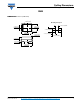
Package SMB (DO-214AA)
Circuit configuration Single
Cathode
Anode
SMB (DO-214AA)
MAJOR RATINGS AND CHARACTERISTICS
SYMBOL CHARACTERISTICS VALUES UNITS
I
F(AV)
Rectangular waveform 1.0 A
V
RRM
90, 100 V
I
FSM
t
p
= 5 μs sine 870 A
V
F
1.0 A
pk
, T
J
= 125 °C 0.63 V
T
J
Range -55 to +175 °C
VOLTAGE RATINGS
PARAMETER SYMBOL VS-MBRS190-M3 VS-MBRS1100-M3 UNITS
Maximum DC reverse voltage V
R
90 100 V
Maximum working peak reverse voltage V
RWM
ABSOLUTE MAXIMUM RATINGS
PARAMETER SYMBOL TEST CONDITIONS VALUES UNITS
Maximum average forward current I
F(AV)
50 % duty cycle at T
L
= 147 °C, rectangular waveform 1.0
A
Maximum peak one cycle
non-repetitive surge current
I
FSM
5 μs sine or 3 μs rect. pulse Following any rated load
condition and with rated
V
RRM
applied
870
10 ms sine or 6 ms rect. pulse 50
Non-repetitive avalanche energy E
AS
T
J
= 25 °C, I
AS
= 0.5 A, L = 8 mH 1.0 mJ
Repetitive avalanche current I
AR
Current decaying linearly to zero in 1 μs
Frequency limited by T
J
maximum V
A
= 1.5 x V
R
typical
0.5 A