
Data Sheet
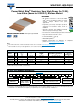

WSLP3921, WSLP5931
www.vishay.com
Vishay Dale
Revision: 24-Jul-17
2
Document Number: 30176
For technical questions, contact: ww2bresistors@vishay.com
THIS DOCUMENT IS SUBJECT TO CHANGE WITHOUT NOTICE. THE PRODUCTS DESCRIBED HEREIN AND THIS DOCUMENT
ARE SUBJECT TO SPECIFIC DISCLAIMERS, SET FORTH AT www.vishay.com/doc?91000
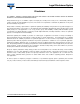
Notes
(1)
Component TCR - total TCR that includes the TCR effects of the resistor element and the copper terminal
(2)
Element TCR - only applies to the alloy used for the resistor element
(3)
Maximum working voltage - the WSL is not voltage sensitive, but is limited by power / energy dissipation and is also not ESD sensitive
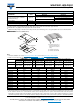
DIMENSIONS in inches (millimeters)
Notes
• 3D models available: 3921 model www.vishay.com/doc?30315; 5931 model www.vishay.com/doc?30317
• Surface mount solder profile recommendations: www.vishay.com/doc?31052
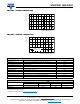
Note
(1)
The full power rating of Power Metal Strip resistors are dependent upon the ability of the circuit board to dissipate the heat energy created
in the resistance element. It is recommended to follow common design practices for power semiconductors that ensure the junction
temperature is maintained with in thermal limits by using large pad surfaces, thermal vias, heavier copper weights, internal layers as well as
other thermal spreading features. The Thermal resistance values provided function in the same manner as junction to terminal temperature.
TECHNICAL SPECIFICATIONS
PARAMETER UNIT
RESISTOR CHARACTERISTICS
WSLP3921 WSLP5931
Component temperature coefficient
(including terminal)
(1)
ppm/°C
± 175 for 0.2 mΩ, 0.5 mΩ, and 0.7 mΩ
± 225 for 0.2 mΩ
± 175 for 0.3 mΩ and 0.5 mΩ
± 75 for 1 mΩ to 4 mΩ, and 2.5 mΩ ± 75 for 1 mΩ to 4 mΩ
Element TCR
(2)
ppm/°C < 20
Operating temperature range °C -65 to +170
Maximum working voltage
(3)
V(P/R)
1/2
MODEL
DIMENSIONS in inches (millimeters) SOLDER PAD DIMENSIONS in inches (millimeters)
LWHT d b l
WSLP3921
0.394 ± 0.010
(10.0 ± 0.254)
0.205 ± 0.010
(5.20 ± 0.254)
0.020
(0.5)
0.080 ± 0.010
(2.00 ± 0.254)
0.106 ± 0.010
(2.70 ± 0.254)
0.244 ± 0.010
(6.20 ± 0.254)
0.220 ± 0.005
(5.60 ± 0.13)
WSLP5931
0.591 ± 0.010
(15.0 ± 0.254)
0.305 ± 0.010
(7.75 ± 0.254)
0.020
(0.5)
0.157 ± 0.010
(4.00 ± 0.254)
0.205 ± 0.010
(5.20 ± 0.254)
0.344 ± 0.010
(8.75 ± 0.254)
0.220 ± 0.005
(5.60 ± 0.13)
GLOBAL MODEL
RESISTANCE VALUE
(mΩ)
THERMAL RESISTANCE
(1)
(°C/W)
“D” THICKNESS
(Inches)
ELEMENT MATERIAL
WSLP3921 0.2 2.5 0.0560 Mn-Cu
WSLP3921 0.3 3.8 0.0510 Mn-Cu
WSLP3921 0.5 5.8 0.0300 Mn-Cu
WSLP3921 1.0 10.9 0.0150 Mn-Cu
WSLP3921 2.0 12.0 0.0270 Fe-Cr
WSLP3921 3.0 20.7 0.0170 Fe-Cr
WSLP3921 4.0 22.8 0.0130 Fe-Cr
WSLP5931 0.2 2.4 0.0490 Mn-Cu
WSLP5931 0.3 3.5 0.0300 Mn-Cu
WSLP5931 0.5 5.7 0.0180 Mn-Cu
WSLP5931 1.0 7.2 0.0330 Fe-Cr
WSLP5931 2.0 13.2 0.0155 Fe-Cr
WSLP5931 3.0 19.3 0.0105 Fe-Cr
H
L
T
W
D
I
d
b
Typical sensing traces
1) Resistive element: Fe-Cr
(element material used is
dependent on resistance
value)
2) Terminal: Solid copper
3) Terminal / element weld
1
2
3