Vision Fitness X20 - X40 - XF40 Frame with Classic / Elegant / Touch Console Service Manual 1
TABLE OF CONTENTS CHAPTER 1: SERIAL NUMBER LOCATION 1.1 Serial Number Location – X20 Frame…………………………………………………………………..…..…….……..…..4 1.2 Serial Number Location – X40 Frame…………………………………………………………………………………..……5 1.3 Serial Number Location – XF40 Frame………………………………………………………………………….…………..6 1.4 Serial Number Location – Classic / Elegant / Touch Console………………………………………………….….………7 CHAPTER 2: ENGINEERING MODE 2.1 Engineering Mode – Classic Console…………………….…………………………………………………….….….……..8 2.
TABLE OF CONTENTS CHAPTER 4: TROUBLESHOOTING 4.1 Troubleshooting – No Power to the Console…………………………………………….…………………….……...…...30 4.2 Troubleshooting – No RPM Display………………………………………………………..………………………………..31 4.3 Troubleshooting – No Resistance or Incorrect Resistance…………………………………………….………………….32 4.4 Troubleshooting – System Will Not Start……………………………………….……………………………………………33 4.5 Troubleshooting – Console No Response....…………………………………………………..………..…………………..34 4.6 Troubleshooting – Touch Panel Issues……….
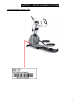
CHAPTER 1: SERIAL NUMBER LOCATION 1.
CHAPTER 1: SERIAL NUMBER LOCATION 1.
CHAPTER 1: SERIAL NUMBER LOCATION 1.
CHAPTER 1: SERIAL NUMBER LOCATION 1.
CHAPTER 2: ENGINEERING MODE 2.1 Engineering Mode – Classic Console 1) To enter Engineering Mode, press and hold the RESISTANCE UP and DOWN keys at the same time for 3-5 seconds until Engineering Menu appears on the display. 2) Use the RESISTANCE UP or DOWN keys to scroll through a list of parameters. 3) Press ENTER to enter a parameter setting. 4) Use the RESISTANCE UP or DOWN keys to change the parameter. 5) Press the START key to save the change to the parameter.
CHAPTER 2: ENGINEERING MODE 2.2 Engineering Mode Overview – Classic Console MODE ENG 0 FUNCTION Display Test DESCRIPTION Start Key – LCD/LED on Stop Key – LCD/LED off Any Other Key - Will show on the display window. Hold the STOP key for 3 seconds to return to the Engineering Menu.
CHAPTER 2: ENGINEERING MODE 2.3 Engineering Mode – Elegant Console 1) To enter Engineering Mode, press and hold the RESISTANCE UP and DOWN keys at the same time for 3-5 seconds until Engineering Menu appears on the display. 2) The Engineering Mode parameter list will be displayed on the screen. 3) Press the ATM style key on either side of the screen to enter the appropriate screen settings. 4) Set all the information using the ATM style keys. 5) Press and hold the “STOP” key to exit Engineering Mode.
CHAPTER 2: ENGINEERING MODE 2.4 Engineering Mode Overview – Elegant Console 2.4.1 Elegant Console – About Tab The Engineering Mode displays the basic parameters of the console, such as Model Type, Software Version, MCB Version, etc… Use the ATM style keys located on both sides of the screen to enter into the parameter. NOTE:Navigation of the other Engineering Mode screens is the same, instructions are not repeated.
CHAPTER 2: ENGINEERING MODE 2.4 Engineering Mode Overview – Elegant Console – Continued 2.4.2 Elegant Console – Settings Tab The Settings Tab includes options for setting Machine Type, Model Type, Energy Saver, First Boot, and Program Speed. Go UP and DOWN to choose Press the key next to "Continue" to enter the next page of settings. Set these settings the same way as Machine Type.
CHAPTER 2: ENGINEERING MODE 2.4 Engineering Mode Overview – Elegant Console – Continued 2.4.3 Elegant Console – Test Tab – Continued Display test – This tab tests the color settings of the console. The console will cycle between red, green, and blue when the Continue key is selected. Hardware Test – This tab allows a service technician to test the RPM sensor and / or the incline motor. Changing a setting should cause the belt and / or the incline motor to operate.
CHAPTER 2: ENGINEERING MODE 2.4 Engineering Mode Overview – Elegant Console – Continued 2.4.3 Elegant Console – Test Tab – Continued Key Test – Press any key to test the function. Audio Test – When this test is chosen, the console chime should sound. 2.4 Engineering Mode Overview – Elegant Console – Continued 2.4.4 Elegant Console – Default Tab The Default Tab includes options for setting Max Workout Time, Default Workout Time, Warm-up Time, Cool Down Time, and Pause Time.
CHAPTER 2: ENGINEERING MODE 2.4 Engineering Mode Overview – Elegant Console – Continued 2.4.5 Elegant Console – Error Log Tab The console will automatically show an error code history for the unit. 2.4.6 Elegant Console – Region Tab The Region Tab includes settings for Month, Day, Year, Time (hour / minute), Language, Country, and Units (miles / kilometers). Press the key next to "Continue" to enter the next page of region settings. Set these region settings using the arrow keys.
CHAPTER 2: ENGINEERING MODE 2.4 Engineering Mode Overview – Elegant Console – Continued 2.4.7 Elegant Console – Service Log Tab The Service Log Tab allows the club / service provider to keep track of the service history.
CHAPTER 2: ENGINEERING MODE 2.5 Engineering Mode – Touch Console 1) To enter Engineering Mode, touch the four corners of the touch screen from 1-4 as shown below. 1 2 4 3 2) An Engineering Mode parameter list will be displayed on the screen. 3) Select the parameter by touching the parameter list. 4) Set all information using the Touch panel. 5) Press the Home key to save the change to the parameter and exit the Engineering Mode.
CHAPTER 2: ENGINEERING MODE 2.6 Engineering Mode Overview – Touch Console 2.6.1 Touch Console – About Tab The About Tab shows the basic parameters of the console, such as Model Type, Software Version, MCB Version etc… NOTE: Press the Home key at any time to return to normal operation.
CHAPTER 2: ENGINEERING MODE 2.6 Engineering Mode Overview – Touch Console – Continued 2.6.2 Touch Console – Settings Tab The Settings Tab used to set the Machine Type, Model and if the Energy Saver is turned on. Setting: Pressing the will automatically bring up the corresponding select block, use the frame type to select the appropriate machine, TREADMILL, ELLIPTICAL or BIKE. Use the same procedure as Machine Type to set the Model Type, Energy Saver, First Boot and Program Speed.
CHAPTER 2: ENGINEERING MODE 2.6 Engineering Mode Overview – Touch Console – Continued 2.6.
CHAPTER 2: ENGINEERING MODE 2.6 Engineering Mode Overview – Touch Console – Continued 2.6.4 Touch Console – Region Tab The Region Tab is used to set Date, Time, Language, Country, and Units. Touch the item that needs to be set, the screen will display a number keypad. Use the keypad to set the information, and press "Home" to save the information. Refer to the figure below: HOME ICON Number setting keypad 2.6.5 Touch Console – Test Tab The Test Tab is used to test the corresponding hardware.
CHAPTER 2: ENGINEERING MODE 2.6 Engineering Mode Overview – Touch Console – Continued 2.6.5 Touch Console – Test Tab – Continued Display Test – Tests the reliability of the LCD and Touch panel. Display Test – Touch Panel Test Use your finger to draw a line following the instructions on the screen. If the test fails, selecting "continue" will bring the user directly into the calibration screen.
CHAPTER 2: ENGINEERING MODE 2.6 Engineering Mode Overview – Touch Console – Continued 2.6.5 Touch Console – Test Tab – Continued Key Test – Tests the functionality of the keys. Select any key on the keypad to display the definition, the function, and the code of the key. If there is no feedback, check the keypad connection with the UCB. Select Continue to exit the test. Audio Test – When the Audio Test key is pressed, the console should chime.
CHAPTER 2: ENGINEERING MODE 2.6 Engineering Mode Overview – Touch Console – Continued 2.6.6 Touch Console – Error Log Tab The console will automatically show an error code history for the unit. 2.6.7 Touch Console – Service Log Tab The Service Log Tab allows the club / service provider to keep track of the service history.
CHAPTER 3: ELECTRICAL DIAGRAMS 3.
CHAPTER 3: ELECTRICAL DIAGRAMS 3.
CHAPTER 3: ELECTRICAL DIAGRAMS 3.
CHAPTER 3: ELECTRICAL DIAGRAMS 3.4 Electrical Diagram – X20 Frame 3.
CHAPTER 3: ELECTRICAL DIAGRAMS 3.
CHAPTER 4: TROUBLESHOOTING 4.1 Troubleshooting – No Power to the Console Symptom: Console does not light up. Reason: 1. The power adaptor is not correct or is defective. 2. The console cable has a bad connection or is defective. 3. The console is defective. Solution: 1. The adaptor for this model is 12V - 2A. Check to make sure the power adaptor on the unit is correct. Test the power adaptor on a known good outlet. Replace the adaptor if it is defective. 2.
CHAPTER 4: TROUBLESHOOTING 4.2 Troubleshooting – No RPM Displayed Symptom: No RPM shown on the console. Reason: 1. Bad connection between the console cable and the console or a damaged cable. 2. The speed sensor wire is damaged or not working. 3. The magnet is not present on the drive pulley. 4. The console is defective. Solution: 1. Check the connection of the console cable at the console; make sure there are no kinks or pinches of the console cable. Replace the cable if any damage is found. 2.
CHAPTER 4: TROUBLESHOOTING 4.3 Troubleshooting – No Resistance or Incorrect Resistance Symptom:1. The resistance is not adjustable during an exercise. 2. The resistance is reverse or much too heavy. Reason: 1. The speed sensor wire is defective. 2. The console cable or ECB motor is defective. 3. The steel rope of the magnet system is not routed correctly. 4. The inside magnet is defective. Solution: 1. Check if the console shows RPM value.
CHAPTER 4: TROUBLESHOOTING 4.3 Troubleshooting - No Resistance or Incorrect Resistance – Continued d. If the ECB motor does move, the resistance can be adjusted. If the resistance is still too heavy, check the gap between the orange block and the bottom of the ECB track. It should be within 1-2 mm of the bottom of the ECB track. If the gap is bigger than 1-2 mm, the resistance will be heavier than normal. Adjust the cable to the correct gap range. X20-X40 X20-X40 XF40 XF40 4.
CHAPTER 4: TROUBLESHOOTING 4.5 Troubleshooting – No Console Response Symptom: The power is on, the console lights up, and a program can be started, but there is no control over the program. Reason: 1. The Machine Type is set incorrectly. 2. There is a MCB error present. 3. The console does not have the correct software. 4. The console is defective. Solution: 1. Enter into Engineering Mode and make sure that the Machine Type is set correctly (see Section 2.2 or 2.4.2). 2.
CHAPTER 4: TROUBLESHOOTING 4.6 Troubleshooting – Touch Panel Issues Symptom: The touch screen is not accurate or invalid. Reason: 1. The screen needs to be calibrated. 2. The touch screen is damaged. 3. The FPC wire does not have a good connection to the UCB. Solution: 1. If the touch screen is not accurate or has a deviation, press the ENTER and STOP keys together for 3-5 seconds to enter the screen calibration mode. Follow the prompts to calibrate the touch screen. 2.
CHAPTER 4: TROUBLESHOOTING 4.7 Troubleshooting – Heart Rate Issues Symptom: The console does not display heart rate or it is consistently inaccurate. Reason: 1. The heart rate grips are not connected correctly. 2. The heart rate wiring is damaged. 3. The heart rate board or console is defective. Solution: 1. Remove the 2 screws holding the 2 halves of the heart rate grip together and check to make sure it is well-connected, with no breaks. 2. Check continuity of the HR grip wiring. a.
CHAPTER 4: TROUBLESHOOTING 4.8 Troubleshooting – iPod Issues Symptom: “Cannot Connect the iPod” is shown on the screen. Reason: 1. The iPod cable is damaged or disconnected. 2. The FFC wire is damaged or disconnected. 3. The iPod board or console is defective. Solution: 11nfir1. Check the iPod cable for damage. Make sure it has a good connection. 2. 2. Check the connection of the FFC wire at the iPod board and UCB. 3. If the FFC and iPod cables are well connected and not damaged, replace the console.
CHAPTER 4: TROUBLESHOOTING 4.9 Troubleshooting – Speaker / Audio Issues Symptom: The speaker or headphones have no sound output. Reason: 1. The speaker wire is not well connected to the UCB. 2. The audio short circuit terminal is missing. 3. The software is obsolete. 4. The head phone wire or board is defective. Solution: 1. Confirm whether the speaker wire is well-connected with the UCB. 2. If well-connected, make sure that the audio output short-circuit terminal is present and tight.
CHAPTER 4: TROUBLESHOOTING 4.10 Troubleshooting – Radio Frequency Issues Symptom: The Radio Frequency Board (RF Board) cannot connect with Passport. Reason: 1. The Passport keys are not functional. 2. The FFC wire is damaged or disconnected. 3. The console is defective. Solution: 1. Make sure that the Passport keys are functional (see Section 2.4.3 or 2.6.5). 2. Confirm whether the FFC wire is well-connected, not broken or damaged. Replace if needed.2. FFC connected to the UCB FPC Connector RF board 3.
CHAPTER 4: TROUBLESHOOTING 4.11 Troubleshooting – Virtual Active Issues Symptom: Cannot play Virtual Active files. Reason: 1. The SD card is not fully seated in the UCB. 2. The software version is not correct on the console. 3. The console is defective. Solution: 1. Confirm if the SD card is firmly seated on the UCB. If not, re-insert the SD card and use adhesive tape to fix it in place. No Good OK 2. If the SD card is inserted correctly, update the Software Version in the console (see Section 5.1). 3.
CHAPTER 5: SOFTWARE UPGRADE GUIDE 5.1 Software Upgrade Procedure 5.1.1 Update File Description OS Update File: NK.rom; Elegant Console Update Software File: DeluxeGUIDeploy.CAB; Touch Console Update Software File: PremierGUIDeploy.CAB OS update file Software update file Configuration file Sub MCU update file * Note: update the software after the OS is updated. 5.1.2 Updating OS and Software * Note: OS files need to distinguish between 7, 10, and 15 inch displays. The OS file names are the same. 1.