
User's Manual

SX127X RF Module User Manual of E19 Series Modules
Copyright ©2012–2017,Chengdu Ebyte Electronic Technology Co.,Ltd
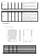
6
7
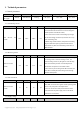
DIO0
Input/Output
Configurable IO port(Please find more on SX127X datasheet)
8
RST
Input
Reset
9
GND
Configurable IO port(Please find more on SX127X datasheet)
10
GND
Configurable IO port(Please find more on SX127X datasheet)
11
VCC
Power supply: 4.75~5.5V (Ceramic filter capacitor is advised to add)
12
SCK
Input
SPI clock
13
MISO
Output
Master output slave input
14
MOSI
Input
Master input slave output
15
NSS
Input
Chip select
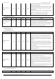
16
TXEN
Input
Radio frequency switch control, make sure the TXEN pin is in
high level, RXEN pin is in low level when transmitting.
17
RXEN
Input
Radio frequency switch control, Make sure the RXEN pin is in
high level ,TXEN pin is in low level when receiving.
18
GND
Ground electrode, connected to the power reference ground
19
ANT
Antenna
20
GND
Ground electrode, connected to the power reference ground
21
GND
Ground electrode, connected to the power reference ground
★ Please find more on SX127X6 datasheet from SEMTECH ★
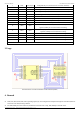
3.Usage
Brief introduction of connection between module and MCU (STM8L)
4. Remark
⚫ DIO0、DIO1、DIO2、DIO3、DIO4、DIO5 is generally purpose I/O, can be configured into multiple function,please check SX1278/SX1276
manual for more details, floating is allowed.
⚫ RST, TXEN, RXEN pin must be connected, in which RST control the reset of chip, TXEN, RXEN pin control RF switch.