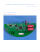
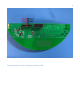
User Manual for VM 1W LoRa modem with dual receiver Last updated on: 10/12/2020 Power pin outs for the module Power Pin 3: GND; Power Pin 4: 3.
Programming header and programming cable
Programming instructions Download and install ST-LINK/V2 in-circuit debugger/programmer for STM8 and STM32 https://www.st.com/en/development-tools/stsw-link004.
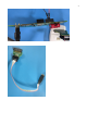
Power up the modem and connect the ST link/V2 programmer to the module as shown in the picture. The mini USB connector of the programmer is connected directly to a PC or laptop.
• click ‘connect to target button’ . • If the connection is successful the debug window looks like this : • Go to file-→open file and load the firmware bin file. If the firmware is loaded successfully the debug window looks like this.
• Click ‘program verify’ icon • A window appears, verify if the settings are similar to what’s shown in the picture • click start, this will start flashing the firmware.
• click ‘disconnect from device’ icon. • Now the programming cable can be removed from the module and the module is ready for testing. Firmware bin file details: The firmware files that will enable transmissions in fixed frequencies are named as follows: • VM_HALFMOON_FCC_LOW (transmit at 902.3Mhz) • VM_HALFMOON_FCC_MID (transmit at 908.5Mhz) • VM_HALFMOON_FCC_HIGH (transmit at 914.9Mhz) The firmware file that will enable the module to hop in 64 channels between (902.3 and 914.
Modulation method This Device uses Frequency Hopping Spread Spectrum (FHSS) as its modulation technique. The list of frequencies are as follows: 902.3 902.5 902.7 902.9 903.1 903.3 903.5 903.7 903.9 904.1 904.3 904.5 904.7 904.9 905.1 905.3 905.5 905.7 905.9 906.1 906.3 906.5 906.7 906.9 Frequency in Mhz 907.1 908.7 907.3 908.9 907.5 909.1 907.7 909.3 907.9 909.5 908.1 909.7 908.3 909.9 908.5 910.1 910.3 910.5 910.7 910.9 911.1 911.3 911.5 911.7 911.9 912.1 912.3 912.5 912.7 912.9 913.1 913.3 913.
Simplified Block Diagram MCU STM32L433xx The STM32L433xx devices are the ultra-low-power microcontrollers based on the high performance Arm® Cortex®-M4 32-bit RISC core operating at a frequency of up to 80 MHz. The Cortex-M4 core features a Floating point unit (FPU) single precision which supports all Arm® single-precision data-processing instructions and data types. It also implements a full set of DSP instructions and a memory protection unit (MPU) which enhances application security.
• • • Automatic RF Sense and CAD with ultra-fast AFC Packet engine up to 256 bytes with CRC Built-in temperature sensor and low battery indicator Power amplifier RFFM6900 2.5V TO 4.2V, ISM BAND, 1W 915MHz Transmit/Receive Module The RFFM6900 is a single-chip front end module (FEM) for applications in the 900MHz and 868MHz.ISM Bands. The RFFM6900 contains an integrated 1 Watt PA, SP3T antenna switch, integrated Tx harmonic filter, Tx thru path, LNA with bypass mode, and matching components.
Integration instructions for host product manufacturers according to KDB 996369 D03 2.2 List of applicable FCC rules CFR 47 FCC PART 15 SUBPART C has been investigated. It is applicable to the modular Transmitter 2.3 Specific operational use conditions This module is stand-alone modular.
INSTRUCTION TO THE USER This equipment has been tested and found to comply with the limits for a class B digital device, pursuant to part 15 of the FCC Rules. These limits are designed to provide reasonable protection against harmful interference in a residential installation. This equipment generates radio frequency energy and if not installed and used in accordance with the instructions, may cause harmful interference to radio communications.