
User manual


Page 28
Chapter 8
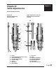
(Figure 8.3)
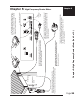
(Figure 8.3) Tightening the
cutter knob in the draw bar.
Zeroing Cutters for Top-Loaded Spindles (see page 15, gure 3.1)
1. Turn the micrometer to zero. This provides a starting point and reference for setting the
depth accurately. It’s important to note that the micrometer should be threaded onto the
spindle housing sufciently to prevent excessive play in the micrometer and nosecone. If there
are too few threads holding the micrometer in place it will move during the engraving process.
The best starting position is 3 or 4 complete revolutions from the top.
CAUTION: When you loosen the setscrew in this step, the cutter may easily fall out of
the spindle and can cause cutter tip damage. Use one hand to hold the cutter before
loosening.
2. With the appropriate cutter installed in the spindle, loosen the setscrew in the brass cutter
knob with a spline wrench (commonly referred to as the cutter wrench).
3. Gently place a piece of metal against the bottom of the nosecone so as to push the cutter
even with the bottom of the nosecone. Now the cutter should be ush with the nosecone.
Retighten the cutter knob setscrew. Your cutter is now zeroed. Rotating the micrometer clock-
wise will adjust the depth of the cut. Each click of the micrometer = .001”.
A full revolution is .025”.
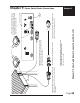
Zeroing Cutters for Top-and-Bottom-Loaded Collet Spindles (see page 15, gure 8.2)
The collet spindle can be used for either top loaded or bottom loaded cutters. To install a top
loaded cutter in the collet spindle, rst set the micrometer to zero. Loosen the knurled draw bar
on the very top of the spindle slightly. Remove the cutter knob from the cutter, and slide the cutter
into the spindle. Place a piece of at material against the bottom of the nosecone and lower the
cutter until it rests against the material. Tighten the draw bar around the cutter, make sure it is
tight. Then reattach the cutter knob to the top of the cutter and screw
it in counterclockwise until secure. Be careful screwing the cutter
knob in, as counterclockwise is the direction to unscrew the draw
bar (see g 8.3). Never use pliers! The cutter depth can be adjusted
by turning the micrometer counter clockwise. Note: If using 2” short
cutters, install them from the bottom. Use the draw bar on the very
top of the spindle to tightly secure the cutter.
A solid collet, if purchased, can be installed in place of the split
collet for burnishing. Install the collet in the bottom of the spindle
and tighten the draw bar rmly. The spindle now acts as a normal
top loaded spindle for ease of operation. The split collet can be
reinstalled when required.