Instruction Manual Table of Contents Safety Instructions -------------------------------------------------- page 2 Chapter 1 Setting up the Vision Cylindrical System-------------------- page 3-6 Chapter 2 Quick Start to Engraving -------------------------------------- page 7-10 Chapter 3 Tips & Tricks ---------------------------------------------------- page 11-14 Chapter 4 Troubleshooting & Maintenance---------------------------- page 15-20 Appendix A— Contacts ---------------------------------------------
SAFETY PRECAUTIONS for The Vision Cylindrical Engraver !"Keep hands clear of the spindle belt during operation. !"Always stop the machine before making any adjustments. !"Keep clear of adjustment knobs located on the rear, left and right side of the table. !"Disconnect the table cable before servicing. !"Do not operate the system with covers removed. !"Wear safety glasses when cutting metal or when operating the system without a vacuum system. !"Use extreme caution when inserting or removing cutters.
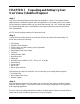
CHAPTER 1 Unpacking and Setting Up Your New Vision Cylindrical Engraver •Step 1 Your Vision Cylindrical Engraver System has been packaged in 2 boxes. You may have received additional boxes if additional accessory items were purchased. If you already own a Vision system and are adding the cylindrical table only, you should have received only 1 box. Check each package for external damage and report it immediately to your freight company and your local area Vision sales representative.
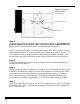
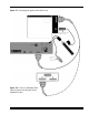
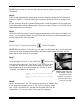
Figure 1.1 • Stylus with packing material (Front View) Head Locking Screws (4) Tail Stock •Step 4. Connect the glass engraver to the system control unit as shown in figure 1.2. If you already own a Phoenix engraver, connect the gray “table” cable to the A/B box as shown in figure 1.2a. Ensure that all of the connections are solid by screwing down the cable screws. NOTES: (1) You have the option of designating which system will be the “A” device.
Figure 1.2 • Connecting the system cables (Rear View) Recirculating Pump Power To 110v wall outlet Figure 1.
•Step 8. Now test the recirculating pump by hitting the AUX ON/OFF key on the control unit. Leave the key in the red/green (AUX) position when finished. The keys on the serial controller are “tri-state” switches with three positions: ON (displaying a green light), OFF (displaying a red light) or AUX (displaying a red/green light). NOTE: The pump may need to be primed. Repeating STEP 8 several times may be necessary to get the liquid to fill the tubes. •Step 9.
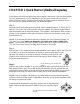
CHAPTER 2 Quick Start to Cylindrical Engraving In this chapter you will go through the easy steps to engrave a coffee mug. A piece has been supplied for you to experiment on. Don’t be disappointed if the first cup you create does not come out perfect. With just a couple of attempts you will master the simple process and techniques and be well on your way to getting the most out of your cylindrical engraver. Step 1. You must turn off limits when you start to use the Vision Cylindrical Engraver.
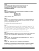
Figure 2.1 • Top view of Vision Cylindrical Engraver with mug (note that mug handle is positioned to the front of the unit carriage adjustment knob carriage spindle tail/head stock adjustment knob tail stock head stock metal bar for moving the tail stock Figure 2.2 • Lowering the carriage with the head release tab. Shown is a close-up view from the right front side of the carriage.
NOTE: Before moving on to the next step, make sure that the carriage is positioned to the left of the tailstock. Step 4. With one hand supporting the carriage, gently lower the carriage by releasing the head release lever as shown in fugure 2.2. Lower the head to the mug surface and rest the feet of the carriage on the mug. We have previously set up the Cylindrical Engraver with a cutter and adjusted it for this quick start. Other cutters may be used and adjustments for this may be found in Chapter 3.
Step 9. Start the Vision program. Using the mouse select FILE and open a NEW JOB. If you have never created a layout with the Vision program, refer to the software manual to familiarize yourself with the basic program features. The following is a sample job: Step 10. Select F5 to create an autolayout. This will greatly simplify the process and give you a perfectly centered layout. Type in the following: Plate width = 2.000". Plate height = 1.000". Number of Lines = 2. Using the mouse, click “okay”.
CHAPTER 3 Tips & Tricks Attempting a new shape for the first time If you cannot determine the actual diameter of the object, select the closest object you are familiar with and use that number. Its helpful to develop a list of diameters for glasses you offer and keep it posted next to the engraver for quick reference. If you are using Libby Glass, the below table lists some common sizes and may be helpful if just getting started.
Hint: Always inspect an object before engraving. On inexpensive glass there may be a seam running from top to bottom. Engraving over the seam may not yield the best results. Sometimes you can rotate the object to get a better area for engraving. Also, if the customer supplied the item to be cut, note with them any defects, scratches or blemishes. You will not want to be held responsible for any of these later.
Rub n’ Buff This simple filler will add class to your engraved items. Many colors are available through your local craft store. Once the item has been engraved, wipe the glass clean and dry. Add a couple beads (about the size of a pea), of rub n’ buff to the glass surface. Rub into the image and wipe clean with a paper towel. Do not leave the rub n’ buff on the surface long or it will become difficult to remove. NOTE: Imperfections in the glass will pick up the rub n’ buff color as well.
maximum engraveable area for a large graphic or message or you can protect the label from the coolant liquid. Simply wrap the label area with plastic wrap (Saran Wrap), and use masking tape to secure the ends. This will keep the label dry during cutting. It will also keep the rub n’ buff off of the label when applying. Securing a wine or champagne bottle is no more difficult than securing a mug. Remove the splash guard on the right side of the unit by removing the two thumbscrews that secure it in place.
CHAPTER 4 Troubleshooting & Maintenance •TROUBLESHOOTING Trouble Condition Possible Cause Corrective Measure System will not move to limits •Is the power cord connected? •Is the power strip/source on? •Connect the power cord securely. •Turn on the main power strip. •Use the software feature Run: Move to Limits to test your limits. Pump does not turn on / has very limited flow •Check to see that enough liquid is in the basin of the engraver. •Check to see if debris is clogging the pump.
• TROUBLESHOOTING (continued) Trouble Condition Possible Cause Corrective Measure No XYZ motion •Drives not on •Emergency Stop Button in •Check LED Ind light, should be green. •Ensure the Emergency Stop Button is in the out position. •Make sure the table cable is plugged into the controller and table.
Zeroing the Diamond (see figure 4.1) STEP 1. Turn the micrometer to zero. This provides a starting point and reference for setting the depth accurately. It’s important to note that the micrometer should be threaded onto the spindle housing sufficiently to prevent excessive play in the micrometer and nosecone. If there are too few threads holding the micrometer in place it will move during the engraving process. The best starting position is 3 or 4 complete revolutions from the top.
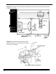
LUBRICATION RAILS• Lightly spray or wipe with 3 in 1—do not use grease. See figure 4.2. LEADSCREW• Lightly spray or wipe with silicone-based lubricant—do not use grease. See figure 4.2. Spray the length of the stainless steel rails and the leadscrew and move the carriage from left to right so as to evenly distribute the lubricant. Figure 4.
Figure 4.
Figure 4.
APPENDIX A Contacts AMACO LIBBEY INC. (AMERICAN ART CLAY COMPANY, INC.) Glassware manufacturer Corporate Headquarters 420 Madison Avenue P.O. Box 10060 Toledo, OH 43699-0060 (419) 727-2100 The maker of Rub ‘n Buff 4717 West 16th Street Indianapolis, IN 46222 (800) 374-1600 ANCHOR HOCKING Specialty glass suppliers 2893 W. Fair Ave.