
Specifications

RF OUTRF OUT
DC 15V INDC 15V IN
OUTPUT
IR
OUTPUT
IR
CABLECABLE
ANTENNAANTENNA
ANTENNA + CABLEANTENNA + CABLE
VIDEOVIDEO
AUDIOAUDIO
L RL R
BB
AA
VIDEOVIDEO
AUDIOAUDIO
L RL R
DD
CC
11
44
33
22
1122
33
44
OUTPUT
IR
OUTPUT
IR
RF OUTRF OUT
DC 15V INDC 15V IN
OUTPUT
IR
OUTPUT
IR
CABLECABLE
ANTENNAANTENNA
ANTENNA + CABLEANTENNA + CABLE
VIDEOVIDEO
AUDIOAUDIO
L RL R
BB
AA
VIDEOVIDEO
AUDIOAUDIO
L RL R
DD
CC
11
44
33
22
1122
33
44
OUTPUT
IR
OUTPUT
IR
Part No. HS-2
2-WAY SPLITTER/COMBINER
5MHz-1GHz All Port DC passing
TM
CHA NN EL VIS I ON
IN
/out
OUT/in
OUT/in
Part No. HS-2
2-WAY SPLITTER/COMBINER
5MHz-1GHz All Port DC passing
TM
CHA NN EL VIS I ON
IN
/out
OUT/in
OUT/in
Part No. HS-4
4-WAY SPLITTER/COMBINER
5MHz-1GHz All Port DC passing
TM
CHA NN EL VIS I ON
IN
/outOUT/in OUT/in
OUT/inOUT/in
Part No. HS-4
4-WAY SPLITTER/COMBINER
5MHz-1GHz All Port DC passing
TM
CHA NN EL VIS I ON
IN
/outOUT/in OUT/in
OUT/inOUT/in
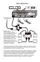
Sat Receiver
Sat Receiver
VCR
VCR
From Cable TV or
Antenna feed
From Cable TV or
Antenna feed
RF Filter
RF Filter
DC Blocks
HS-4
DC Passing Splitter
HS-2
DC Passing Combiner
IR Emitter
Camera
Camera
Camera
Camera
HS-2
Combiner
IR receiver
IR-4100
IR Coax Adaptor
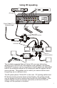
Using IR repeating
Basic Application
Check the signal from your video sources to make sure you have a good
picture before connecting to the modulator. Connect the RF output from
the modulator as shown in the diagram above.
It is important to balance the RF signal levels before joining them together
in the combiner. It may be necessary to amplify the cable/antenna signal
to match it with the high output of the modulator. If the cable/antenna
signal is too low in relation to the modulator, you will notice that the
cable/antenna signal is degraded when the modulator is connected.
Simply amplify the cable/antenna signal to resolve the problem.
The modulator supports Channel Vision’s IR over coax technology
allowing up to 8 IR-4100 IR coax adaptors to be installed in the system.
Standard IR receivers can be connected so that IR signals are transmitted
back to the modulator where the IR emitters will flash the signals into the
source devices. This enables you to control your source devices even
though they are in a different room.
This IR system places 12Volts DC on the coax. DC passing splitters and
DC blocks must be used as shown in the diagram. DC voltage should
only be allowed to flow to locations that have an IR-4100 installed. If the
system detects a short (or improper connection) it will shut off the IR
voltage until the problem is corrected.
Helpful Tips:
The use of an RF filter is
recommended for this kind of
setup. It will help remove
unwanted signals from the
cable or antenna feed, allowing
the modulator to perform
without interference. It also
helps provide the isolation
needed to prevent your system
from interfering with your
neighbors TV reception.
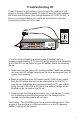
5
4
TM
CHA NNE L VIS ION
From IR
engine
IR-4100
IR coax adaptor
To TV
IR receiver
1
2
3
4
5
6
7
8
9
0
P
w
e
o
r