Vision Engravers and Routers PRE-Installation Guide © 2014 Vision Engraving & Routing Systems Revised: 8/4/2014
Vision Engravers and Routers PRE-Installation Guide © 2014 Vision Engraving & Routing Systems All rights reserved. No parts of this work may be reproduced in any form or by any means - graphic, electronic, or mechanical, including photocopying, recording, taping, or information storage and retrieval systems - without the written permission of the publisher. Products that are referred to in this document may be either trademarks and/or registered trademarks of the respective owners.
Contents 3 Table of Contents Part I Introduction and Computer Requirements 4 Part II General Electrical and Facility Requirements by Model 5 Part III Express and VE-810 6 1 Express ................................................................................................................................... Layout Diagram 7 2 VE-810...................................................................................................................................
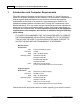
1 Vision Engravers and Routers PRE-Installation Guide Introduction and Computer Requirements This guide contains information to prepare the new owner of a Vision Engraver or Router for the proper installation of their machine.
Introduction and Computer Requirements 2 5 General Electrical and Facility Requirements by Model Machine Model Requirements Express, VE-810, 1612, 1624 Engraver, 2424, 2448, One 110 VAC 15 Amp, or One 220 VAC 10 MAX and MAX Pro Amp Single Phase 1624R, 2525 and 2550 Router - T-Slot Table With High Frequency Router Head One 110 VAC 15 Amp, or One 220 VAC 10 Amp Single Phase AND One 220 VAC 30 Amp Single Phase With Engraving Head One 110 VAC 15 Amp, or One 220 VAC 10 Amp Single Phase With NSK High Fre
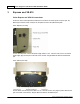
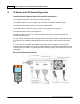
3 Vision Engravers and Routers PRE-Installation Guide Express and VE-810 Vision Express and VE-810 Connections On the rear of the Vision Express and VE810, there are three connection ports. The power port, the Ethernet port and the remote on/off port for the optional Vacuum Chip Removal System. Vision Express (rear view) For the Vision Express: Connect the power supply cable to a 110 - 220 VAC source, then connect the power supply plug into the port on the back of the machine.
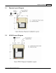
Express and VE-810 3.1 Express Layout Diagram 3.
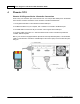
4 Vision Engravers and Routers PRE-Installation Guide Phoenix 1212 Phoenix 1212 Engraver/Series 4 Controller Connections There is only one connection port on the Phoenix 1212. It is a 25 pin Table Cable port on the left side of the machine. All other connections on the machine's controller are listed below. 1. The engraver's Pendant is connected to the Pendant cable port. 2. The Ethernet Cable from your computer, hub or network is connected to the Ethernet port. 3.
Phoenix 1212 4.
5 Vision Engravers and Routers PRE-Installation Guide 16 Series and 24 Series Engravers 16 and 24 Series Engraver/Series 4 Controller Connections 1. The engraver's Pendant is connected to the Pendant cable port. 2. The Ethernet Cable from your computer, hub or network is connected to the Ethernet port. 3. The Auxiliary Table Cable is used on the 24 Series engraver ONLY. 4. The Table Cable connects from 25 pin connector on the engraver to the Table port. 5.
16 Series and 24 Series Engravers 5.
5.
16 Series and 24 Series Engravers 6 16 Series and 25 Series Routers 6.1 High Frequency Router Head 13 High Frequency Router Head Wiring Connections 1. The controller Pendant is connected to the Pendant port on the controller. 2. The Ethernet Cable from your computer, hub or network is connected to the Ethernet port on the controller 3. The Auxiliary Table Cable is used on the 25 Series machines ONLY. It connects the Serial Table Connector on the machine to the Aux Table port on the controller. 4.
Vision Engravers and Routers PRE-Installation Guide Wiring Connections for Inverter (used with High Frequency Router Head only) NOTE: The Auxiliary Power Cable is pre-wired on all 16 and 25 Series Routers. Remove Inverter Cover and feed the Auxiliary Power Cable through hole in bottom of Inverter. Connect the three black wires labeled, T1, T2 and T3, to their respective connection points. Connect the Green (Ground) wire to the connection point shown.
16 Series and 25 Series Routers 15 Carriage Wiring Connections The Motor Plug connects to the Spindle Port on the back of the Carriage. Carriage (rear view) Mounting the Inverter on the 25 Series Table Stand The Inverter is mounted on the top-left corner of the machine's stand. There are two flanges mounted on the rear of the inverter. These flanges are placed in the inside of the stand's legs. Screws are included with the inverter to secure the inverter to the stand.
6.2 Vision Engravers and Routers PRE-Installation Guide Engraving Head Engraving Head Wiring Connections 1. The controller Pendant is connected to the Pendant port on the controller. 2. The Ethernet Cable from your computer, hub or network is connected to the Ethernet port on the controller 3. The Auxiliary Table Cable is used on the 25 Series machines ONLY. It connects the Serial Cable Port on the machine to the Aux Table port on the controller. 4.
16 Series and 25 Series Routers Carriage Wiring Connections The Motor Plug connects to the Spindle Port on the back of the Carriage.
6.
16 Series and 25 Series Routers 6.
Vision Engravers and Routers PRE-Installation Guide © 2014 Vision Engraving & Routing Systems
16 Series and 25 Series Routers © 2014 Vision Engraving & Routing Systems 21
7 Vision Engravers and Routers PRE-Installation Guide MAX and MAX PRO Max and Max Pro Connections The Vision Max and Max Pro machines have an integrated controller inside the base of the machine. The machines need to have the following cables connected to the controller. 1. The engraver's Pendant is connected to the Pendant cable port. 2. The Ethernet Cable from your computer, hub or network is connected to the Ethernet port. 3.
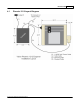
MAX and MAX PRO 7.1 23 MAX and MAX PRO Layout Diagram * This dimension is added to allow for clearance on the rear of the machine for cables and for air flow to the cooling fan.
8 Vision Engravers and Routers PRE-Installation Guide VR48 Router Unloading the Crate - IMPORTANT INFORMATION Please follow these guidelines when unloading the crated machine from the freight truck. The VR48 is shipped in a large framed crate with all accessories loaded under the machine. The crate presents a significant tip hazard when using lower capacity fork lifts.
VR48 Router 8.1 25 Requirements Electrical Connections 1. A qualified and licensed electrician must be used to complete all wiring and grounding of the machine according to all state, local, and national electrical codes. 2. Make sure all Junction Boxes and Outlets are mounted according to all state, local and national electrical codes. 3. Junction Box #1 (50 Amp, 220 VAC, Single Phase) will power the router table, spindle, and controls.
Vision Engravers and Routers PRE-Installation Guide Locating the Router 1. A doorway of at least 80 inches wide and 80 inches high is required in order for the router to be moved into your facility. 2. Locate machine indoors on a flat surface and on a solid foundation. 3. Temperature must remain between 40°F and 85°F. 4. Do not expose machine to direct sunlight, rain, vibration, dampness, or explosive environments. 5.
VR48 Router 27 Leveling the machine 1. Make sure the machine has been properly located at your work-site. 2. It is not necessary to bolt your machine to the floor in your facility. However, a solid, stable foundation is required to support the machine's weight. 3. There should be a leveling bolt in each of the four machine legs. 4. Place a precision leveling gauge on the machine's table top and adjust the leveling bolts until the machine is level in both the horizontal and vertical directions.
8.2 Vision Engravers and Routers PRE-Installation Guide Wiring Connections The Main Power Switch is located on the left side of the VR48. The main power supply is connected to the Main Electrical Box on the left side of the VR48. Remove the cover and make the connections as shown below. Ground is connected to the bare wire and common leads are connected to the two shielded wires. The supply for this connection is Junction Box #1 (220 VAC, Single Phase).
VR48 Router 29 On the front of the control box for VR48 Router, there are four connection ports; One is an Ethernet port used to connect your computer or network to the on-board Series 4 Controller, the second is for the Pendant, the third is a USB port used to connect a computer to the VR48 when using the DACS Camera System, and the fourth is to connect the Remote Start Switch for the Dust Collector System.
Vision Engravers and Routers PRE-Installation Guide The Dust Collector Remote Start Switch will need to be connected. For ease of operation, a remote start switch and cables can be used to turn on the dust collector automatically when a job is being run. The supply for this connection is from Outlet #1 (220 VAC, Single Phase, 20 Amp).
VR48 Router 31 Wiring for this switch is shown below. The input and output wires should be connected as shown. Both input and output ground wires can be connected to the single GND location shown. The switch can be wall mounted at a location convenient for the user. The Remote Start Cable is connected to the Remote Start Port on the front of the machine's control box.
8.3 Vision Engravers and Routers PRE-Installation Guide Vacuum Pump Connections - Vacuum Table Models Only The Main Vacuum Port for the VR48 is located at the foot of the machine. To connect the vacuum pump to the machine, use the supplied 3" diameter vacuum hose and connect one end to the vacuum pump and the other end to the Main Vacuum Port on the machine. The vacuum pump has been equipped with an electrical connector designed for a 40 amp, 220 VAC, 3 phase power supply.
VR48 Router 8.
Vision Engravers and Routers PRE-Installation Guide Vacuum Table Models © 2014 Vision Engraving & Routing Systems