
Installation guide


Vision Engravers and Routers PRE-Installation Guide10
© 2014 Vision Engraving & Routing Systems
5 16 Series and 24 Series Engravers
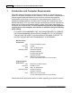
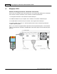
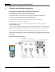
16 and 24 Series Engraver/Series 4 Controller Connections
1. The engraver's Pendant is connected to the Pendant cable port.
2. The Ethernet Cable from your computer, hub or network is connected to the Ethernet port.
3. The Auxiliary Table Cable is used on the 24 Series engraver ONLY.
4. The Table Cable connects from 25 pin connector on the engraver to the Table port.
5. The Spindle Cable connects to the Spindle port.
6. The Power Cable connects a 110 - 220 VAC electrical source to the controller and powers the
controller, table and spindle.
7. If your machine is equipped with the optional Vacuum Chip Removal System, a remote On/Off cable
is connected to the controller to automatically turn the vacuum pump on and off when the job is being
run.
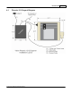
8. *If your machine is equipped with the optional NSK High Frequency Spindle, an second 25 pin
connector will be included with your controller. The NSK Spindle is controlled by the NSK Spindle Cable
connected to this port. NOTE - the Spindle Cable to the standard engraving motor will not be used in this
configuration.
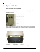
Series 4 Pendant and Controller