
Installation guide


Vision Engravers and Routers PRE-Installation Guide14
© 2014 Vision Engraving & Routing Systems
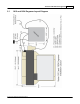
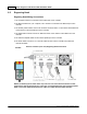
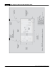
Wiring Connections for Inverter (used with High Frequency Router Head only)
NOTE: The Auxiliary Power Cable is pre-wired on all 16 and 25 Series Routers.
Remove Inverter Cover and feed the Auxiliary Power Cable through hole in bottom of Inverter. Connect
the three black wires labeled, T1, T2 and T3, to their respective connection points. Connect the Green
(Ground) wire to the connection point shown. Connect the Main Power Cable to a 220VAC source and
connect the MOD/BUS Cable to the machine controller's MOD/BUS port.