
Installation guide


Vision Engravers and Routers PRE-Installation Guide16
© 2014 Vision Engraving & Routing Systems
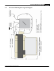
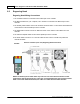
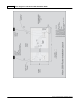
6.2 Engraving Head
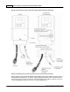
Engraving Head Wiring Connections
1. The controller Pendant is connected to the Pendant port on the controller.
2. The Ethernet Cable from your computer, hub or network is connected to the Ethernet port on the
controller
3. The Auxiliary Table Cable is used on the 25 Series machines ONLY. It connects the Serial Cable Port
on the machine to the Aux Table port on the controller.
4. The Table Cable connects from 25 Pin Table Connector on the machine to the Table Port on the
controller
5. The machine's Spindle Cable connects to the Spindle port on the controller.
6. The Power Cable connects a 110 - 220 VAC electrical source to the controller and powers the
controller and table.
Series 4 Controller (rear view) Engraving Head Connections
Pendant
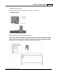
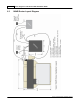
NOTE: The Auxiliary Power Cable which is pre-wired on all 16 and 25 Series Routers is NOT
used with the Engraving Head. If your router was not equipped with the High Frequency Router
Head or the Porter Cable Router Head, this cable can remain disconnected at all times.