ENGLISH TM-UST TECHMOUNT OWNERS MANUAL TM-UST TECHMOUNT GUIDE DE L’UTILISATEUR TM-UST TECHMOUNT MANUAL DE USUARIO TM-UST TECHMOUNT GEBRUIKERSHANDLEIDING BEDIENUNGSANLEITUNG TM-UST TECHMOUNT TM-UST TECHMOUNT MANUALE DEL PROPRIETARIO TM-UST TM-UST TECHMOUNT: INSTRUKCJA OBSŁUGI installation:innovation
ENGLISH TM-UST TECHMOUNT OWNERS MANUAL Congratulations on your choice of the Vision TM-UST TECHMOUNT. In order to obtain the best performance please be sure to read this owner’s manual and use your product only in accordance with the instructions. An electronic version of this manual and further information can be found on www.visionaudiovisual.com CONFORMITY The product described in this owner’s manual is in compliance with RoHS (EU directive 2002/95/EC), and WEEE (EU directive 2002/96/EC) standards.
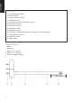
ENGLISH Contents 1 x 2-part Boom Assembly 1 x Wall Assembly 1 x Universal Spider Fitting 1 x H50 Pin-Hex key 4 x M2.5 43mm pan slot for Optoma & Acer 4 x M3 43mm screws 4 x M4 43mm screws 4 x M5 43mm screws 4 x M6 43mm screws 6 x ST8 50mm Ceiling Fixtures with rawl plugs for wall attachment 1 x 2-part Wall Plate Cover 6 x Wall Plate Inserts 1 x Boom Cover Bracket Parts 1. Bolts 2. Wall Plate 3. Boom Part – section 1 4. Boom Part – section 2 5.
ENGLISH INSTALLATION INSTRUCTIONS 1. Attach the wall plate to the wall using six appropriate fixtures. When you have attached the wall plate you will have 170mm of height adjustment, but it is still important to position it carefully. In rooms with low ceilings the height you can mount the screen/whiteboard will be limited by the ceiling height so the bracket should be mounted as close to the ceiling as possible.
ENGLISH 2. Fit section 1 of the boom to the wall plate, and fix tightly using the four pin-hex bolts included. 1. Section 1 of boom 3. Fit the universal “spider” fitting included to the projector as shown by threading the 43mm screws included through the hollow screw already in place on each “leg” of the spider. The Hitachi requires M6 screws, and the Sanyo requires M4. Other screw sizes are included to cater for other projectors. Fit the spider to section 2 of the boom as shown: 1.
ENGLISH 5. Plug power into the projector and turn it on. Follow these steps to setup the projector: 1. Adjust the boom length so that the projected image matches the screen WIDTH (don’t worry about height yet), making sure the projector lens is exactly in the centre of the screen. Note once you have done this adjustment for screens/whiteboards less than 77” (diameter) or 1500mm (wide), section 1 may protrude beyond the rear of the projector and may require shortening. In this case follow this process: 1.
ENGLISH 7. Route the power and inputs cables as shown and clip the covers into place: 1. Cable routing at top and bottom of wall plate 1. Wall plate cover 2. Boom cover 3. Wall plate inserts (use to cover the boom adjustment range hole on the wall cover) ALTERNATIVE EXTENSION POLE FITTING The TM-UST can be extended to up to 1.5m for short throw projectors. This is achieved by fitting the extension pole to section 1, then fitting section 2 to the extension pole.
ENGLISH WARRANTY This product comes with a 2-year return to base warranty, effective from the date of purchase. This warranty applies only to the original purchaser and is not transferable. For the avoidance of doubt, this will be taken from the information held by the appointed national distributor at the point of sale.
8
FRANÇAIS TM-UST TECHMOUNT GUIDE DE L'UTILISATEUR Merci d'avoir acheté Vision TM-UST TECHMOUNT. Afin d'obtenir les meilleures performances du produit, s'assurer d'avoir lu ce guide d'utilisateur et d'avoir respecté les instructions avant son utilisation. Pour télécharger la version électronique de ce guide et obtenir plus d'informations, consulter notre site Internet www.visionaudiovisual.
FRANÇAIS Éléments 1 support mobile en deux pièces 1 ensemble mural 1 support-étoile universel 1 boulon de sécurité « pin-hex » 4 x vis à tête cylindrique large fendue M2,5 de 43 mm d'Optoma & Acer 4 vis M3 de 43 mm 4 vis M4 de 43 mm 4 vis M5 de 43 mm 4 vis M6 de 43 mm 6 plafonniers à crochets pour fixation murale 1 couvercle en deux pièces pour la plaque murale 6 douilles filetées pour la plaque murale 1 couvercle pour le support mobile Pièces du support de fixation 1. Boulons 2. Plaque murale 3.
1. Fixer la plaque murale au mur en utilisant les dispositifs de fixation appropriés. Après avoir fixé la plaque murale, on obtient un ajustement vertical de 170 mm, mais il est toujours nécessaire de la positionner soigneusement. La hauteur nécessaire pour monter l'écran / le tableau blanc sera limitée dans les pièces ayant un plafond bas. Il faut donc installer le support de fixation le plus près possible du plafond.
FRANÇAIS 2. Insérer la partie 1 du support mobile dans la plaque murale, puis serrer fermement en utilisant les boulons de sécurité « pin-hex ». 1. Partie 1 du support mobile 3. Insérer le support-étoile universel fourni (voir illustration ci-dessous), puis fileter les vis de 43 mm fournies dans les vis creuses déjà installées sur chaque « bras » du supportétoile. La marque Hitachi nécessite des vis de type M6 tandis que Sanyo nécessite des vis de type M4.
FRANÇAIS 5. Brancher le projecteur à une source d'alimentation électrique et le mettre en marche. Suivre les étapes d''installation du projecteur suivantes : 1. Ajuster la longueur du support mobile afin que la largeur de l'image projetée soit égale à celle de l'écran (ne pas s'occuper de la hauteur pour l'instant) et s'assurer que l'objectif se trouve exactement au centre de l'écran.
FRANÇAIS 7. Passer les câbles d'entrée et d'alimentation (voir illustration ci-dessous), ensuite mettre le couvercle. 1. Cheminement des câbles en haut et en bas de la plaque murale 1. Couvercle de la plaque murale 2. Couvercle du support mobile 3. Douilles filetées de la plaque murale (utilisées pour couvrir les trous d'ajustement du support mobile sur le couvercle mural) EXTENSION SUPPLÉMENTAIRE DU SUPPORT MOBILE Le TM-UST peut être rallongé de plus de 1,5 m pour les projecteurs à projection courte.
FRANÇAIS GARANTIE Ce produit est garanti 2 ans à compter de la date d'achat. La présente garantie s'applique uniquement à l'acheteur initial et n'est en aucun cas cessible. Par soucis de clarté, cela sera repris par les informations détenues par le distributeur national désigné , que vous pouvez consulter au point de vente.
16
ESPAÑOL MANUAL DEL PROPIETARIO DE TM-UST TECHMOUNT Enhorabuena por haber adquirido el TM-UST TECHMOUNT de Vision. A fin de obtener el mejor rendimiento, le rogamos que lea este manual del propietario y utilice el producto únicamente de acuerdo con las instrucciones. En el sitio Web www.visionaudiovisual.com podrá encontrar una versión electrónica de este manual, así como información adicional.
ESPAÑOL Contenido 1 x Conjunto de montaje del brazo 2 piezas 1 x Conjunto de montaje en la pared 1 x Accesorio de cruceta universal 1 x Llave macho hexagonal H50 4 x Tornillo de cabeza plana con ranura M2.
ESPAÑOL INSTRUCCIONES DE INSTALACIÓN 1. Acople la placa de pared a la pared con seis dispositivos de sujeción adecuados. Cuando haya colocado la placa de pared dispondrá de 170 mm para ajustar la altura, aunque es importante colocarla con cuidado. En estancias con techos bajos, la altura a la que puede montar la pantalla/pizarra electrónica está limitada por la altura del techo. Por lo tanto, el soporte se debe montar lo más cerca del techo que sea posible.
ESPAÑOL 2. Coloque la sección 1 del brazo en la placa de pared y sujétela con firmeza utilizando los cuatro pasadores hexagonales que se incluyen. 1. Sección 1 del brazo 3. Coloque el accesorio de cruceta universal que se incluye en el proyecto tal como se muestra. Para ello, enrosque los tornillos de 43 mm que se incluyen en los tornillos huecos que ya están colocados en cada "pie" del accesorio de cruceta. El modelo Hitachi necesita tornillos M6 y el modelo Sanyo necesita M4.
ESPAÑOL 5. Conecte el proyector a la alimentación eléctrica y enciéndalo. Siga estos pasos para configurar el proyector: 1. Ajuste la longitud del brazo de forma que la imagen proyectada coincida con el ANCHO de la pantalla (no se preocupe por la altura todavía) y compruebe que la lente del proyector está situada justo en el centro de la pantalla.
ESPAÑOL 7. Guíe los cables de electricidad y de entrada tal como se indica y coloque las tapas en su sitio: 1. Recorrido del cable en la parte superior e inferior de la placa de pared. 1. Tapa de la placa de pared. 2. Tapa del brazo. 3. Inserciones de la placa de pared, que se utilizan para cubrir el orificio del rango de ajuste del brazo en la tapa de la pared. COLOCACIÓN DEL VÁSTAGO DE EXTENSIÓN ALTERNATIVO El TM-UST se puede alargar hasta 1,5 m para proyectores de distancia corta.
ESPAÑOL GARANTÍA Este producto incluye una garantía de devolución de dos años que entra en vigor a partir de la fecha de compra. Esta garantía sólo se aplica al comprador original y no es transferible. Para evitar cualquier duda, este dato se obtendrá de la información que posee el distribuidor nacional designado en el punto de venta.
24
NEDERLANDS TM-UST TECHMOUNT GEBRUIKERSHANDLEIDING Gefeliciteerd met uw aankoop van de Vision TM-UST TECHMOUNT. Lees deze gebruikershandleiding en gebruik uw product alleen in overeenstemming met de aanwijzingen voor een optimale prestatie. U vindt een elektronische versie van deze handleiding en verdere informatie op www.visionaudiovisual.
NEDERLANDS Inhoud 1 x 2-delige armassemblage 1 x muurassemblage 1 x universeel 'spin' hulpstuk 1 x H50 Pin zeshoekige ringsleutel 4 x M2.5 43mm kruiskopschroef voor Optoma & Acer 4 x M3 43mm schroeven 4 x M4 43mm schroeven 4 x M5 43mm schroeven 4 x M6 43mm schroeven 6 x ST8 50mm plafondbevestingsmaterialen met plugs voor bevestiging aan de muur 1 x 2-delig muurplaatdeksel 6 x muurplaatinzetstukken 1 x armplaat Onderdelen steun 1. Bouten 2. Muurplaat 3. Onderdeel arm – sectie 1 4.
NEDERLANDS INSTALLATIE-INSTRUCTIES 1. Bevestig de muurplaat met de zes juiste bevestigingsmaterialen aan de muur. Nadat u de muurplaat heeft bevestigd, is er nog een verticale speling van 170 mm. Het blijft echter belangrijk dat u de muurplaat zorgvuldig op zijn plaats brengt. Indien u laag plafond heeft, is er maar beperkte ruimte om het scherm/whiteboard op te hangen, dus dient u de steun zo dicht mogelijk onder het plafond te hangen.
NEDERLANDS 2. Bevestig sectie 1 van de arm stevig aan de muurplaat met de vier meegeleverde Pin zeshoekige bouten. 1. Sectie 1 van arm 3. Bevestig het universele 'spin' hulpstuk dat bij de projector is meegeleverd door de meegeleverde 43 mm schroeven door de holle schroeven te steken die zich al in elke 'poot' van de spin bevinden (zie afbeelding). Voor de Hitachi zijn M6-schroeven nodig en voor de Sanyo M4-schroeven. De overige meegeleverde schroefmaten zijn bedoeld voor andere projectoren.
NEDERLANDS 5. Steek de stekker in de projector en zet hem aan. Volg deze stappen om de projector in te stellen: 1. Pas de armlengte aan, zodat het geprojecteerde beeld net zo groot is als de BREEDTE van het scherm (let nog niet op de hoogte). Zorg er daarbij voor dat de lens van de projector zich precies in het midden van het scherm bevindt.
NEDERLANDS 7. Leid de stroom- en invoerkabels zoals op de afbeelding en klem de deksels weer op hun plaats: 1. Kabelgeleiding aan de boven- en onderkant van de muurplaat 1. Muurplaatdeksel 2. Armdeksel 3. Muurplaatinzetstukken (gebruikt om de gaten voor de armaanpassingen op het muurdeksel af te dekken) ALTERNATIEVE BEVESTIGING MET VERLENGSTUK De TM-UST kan tot 1,5 m verlengd worden voor Short Throw projectoren.
NEDERLANDS GARANTIE Dit product heeft een retourgarantie van twee jaar beginnend op de dag van aankoop. Deze garantie geldt alleen voor de oorspronkelijke koper en kan niet worden overgedragen. Om enige twijfel te voorkomen is deze informatie gebaseerd op de informatie van de aangewezen nationale distributeur op het verkooppunt.
32
DEUTSCHE BEDIENUNGSANLEITUNG TM-UST TECHMOUNT Herzlichen Glückwunsch zum Kauf des Vision TM-UST TECHMOUNT! Um die bestmögliche Funktionalität Ihres Produkts zu erzielen, lesen Sie diese Bedienungsanleitung aufmerksam durch und verwenden Sie das Produkt entsprechend den gegebenen Anweisungen. Unter www.visionaudiovisual.com finden Sie die elektronische Version dieser Bedienungsanleitung sowie weitere Informationen.
DEUTSCHE Lieferumfang 1 x 2-teiliges Armstück 1 x Wandstück 1 x universelle Spinnenhalterung 1 x H50 Stift-Inbus 4 x M2,5 43-mm-Linsenkopfschraube mit Schlitz für Optoma & Acer 4 x M3 43-mm-Schrauben 4 x M4 43-mm-Schrauben 4 x M5 43-mm-Schrauben 4 x M6 43-mm-Schrauben 6 x ST8 50-mm-Deckenbefestigungen mit Wanddübeln zur Wandmontage 1 x 2-teilige Wandplattenabdeckung 6 x Wandplatteneinsätze 1 x Armabdeckung Halterungsteile 1. Schrauben 2. Wandplatte 3. Armteil – Abschnitt 1 4. Armteil – Abschnitt 2 5.
DEUTSCHE MONTAGEANLEITUNG 1. Bringen Sie die Wandplatte mit sechs dafür geeigneten Befestigungen an der Wand an. Nach Anbringung der Wandplatte kann die Höhe noch um bis zu 170 mm verändert werden. Dennoch ist bei der Positionierung auf größtmögliche Genauigkeit zu achten. In niedrigen Räumen wird die maximale Höhe, in der die Bildwand/das Whiteboard befestigt werden kann, von der Höhe der Decke bestimmt. Daher sollte die Halterung so nahe wie möglich an der Decke angebracht werden.
DEUTSCHE 2. Bringen Sie Abschnitt 1 des Arms an der Wandplatte an und befestigen Sie ihn mithilfe der vier beiliegenden Stift-Inbusschrauben. 1. Armabschnitt 1 3. Verbinden Sie die beiliegende universelle Spinnenhalterung entsprechend der Abbildung mit dem Projektor, indem Sie die beiliegenden 43 mm-Schrauben in die Hohlschrauben eindrehen, die sich jeweils an einem Bein der Spinnenhalterung befinden.
DEUTSCHE 5. Schließen Sie das Netzkabel am Projektor an und schalten Sie ihn ein. Befolgen Sie zur Einstellung des Projektors die folgenden Schritte: 1. Wählen Sie die Armlänge so, dass das projizierte Bild die BREITE der Bildwand vollständig ausfüllt (die Höhe wird in einem späteren Arbeitsschritt angepasst) und stellen Sie sicher, dass sich die Linse des Projektors exakt in der Mitte der Bildwand befindet.
DEUTSCHE 7. Führen Sie die Netz- und Eingangskabel entsprechend der Abbildung und setzen Sie die Abdeckungen auf: 1. Kabelführung ober- und unterhalb der Wandplatte 1. Wandplattenabdeckung 2. Armabdeckung 3. Wandplatteneinsätze (zur Abdeckung des Armeinstellungslochs an der Wandabdeckung) ALTERNATIVE VERLÄNGERUNGSARMHALTERUNG Das TM-UST kann für Ultra-Nah-Projektoren um bis zu 1,5 m verlängert werden. Hierfür muss Abschnitt 1 mit dem Verlängerungsarm und dieser mit Abschnitt 2 verbunden werden.
DEUTSCHE GARANTIE Auf dieses Produkt wird eine 2-jährige Rückgabegarantie ab Kaufdatum gewährt. Diese Garantie gilt nur für den ursprünglichen Käufer und kann nicht übertragen werden. Im Zweifelsfall wird dies anhand der Informationen entschieden, die dem für das jeweilige Land zuständigen Vertragshändler am Verkaufsort vorliegen.
40
ITALIANO TM-UST TECHMOUNT MANUALE DEL PROPRIETARIO Congratulazioni per aver scelto TM-UST TECHMOUNT di Vision. Per ottenere le migliori prestazioni, leggere questo manuale e utilizzare il prodotto seguendo attentamente le istruzioni ivi riportate. Una versione elettronica di questo manuale e ulteriori informazioni sono reperibili all'indirizzo www.visionaudiovisual.
ITALIANO Contenuto 1 x kit di montaggio per braccio a due elementi 1 x kit di montaggio per parete 1 x dispositivo di fissaggio universale a ragno 1 x chiave a brugola H50 4 x viti a taglio M2.
ITALIANO ISTRUZIONI PER L'INSTALLAZIONE 1. Fissare la piastra a muro alla parete mediante sei dispositivi di fissaggio idonei. Una volta fissata la piastra a muro, sono disponibili 170mm per la regolazione dell'altezza, ma è comunque importante posizionarla con attenzione. Negli ambienti con soffitto basso, l'altezza a cui si può montare lo schermo/la lavagna bianca sarà limitata dall'altezza del soffitto, pertanto la staffa dovrà essere montata il più vicino possibile al soffitto.
ITALIANO 2. Montare la sezione 1 del braccio alla piastra a muro e fissarla saldamente con i quattro bulloni a brugola. 1. Sezione 1 del braccio 3. Montare il dispositivo di fissaggio universale a ragno al proiettore come mostrato, infilando le viti di 43mm fornite a corredo nella vite forata già posta su ogni "arto" del dispositivo a ragno. Per Hitachi utilizzare viti M6, per Sanyo viti M4. Sono fornite viti di altre dimensioni per diversi tipi di proiettori.
ITALIANO 5. Collegare il proiettore alla corrente e accenderlo. Procedere come segue per impostare il proiettore: 1. Regolare la lunghezza del braccio in modo che l'immagine proiettata corrisponda all'AMPIEZZA dello schermo (per il momento trascurare l'altezza), assicurandosi che l'obiettivo del proiettore sia esattamente al centro dello schermo.
ITALIANO 7. Far passare la corrente e inserire i cavi come mostrato; infine, sistemare le coperture al loro posto: 1. Cavo che passa dalla parte superiore e inferiore della piastra a muro 1. Copertura della piastra a muro 2. Copertura del braccio 3. Inserti della piastra a muro (per coprire l'apertura sulla copertura della parete per la regolazione del braccio) ASTA DI PROLUNGA ALTERNATIVA Qualora siano in uso proiettori short throw, il TM-UST può essere allungato sino a 1,5m.
ITALIANO GARANZIA Il presente prodotto è coperto da 2 anni di garanzia con formula "return to base" con decorrenza dalla data di acquisto. Tale garanzia copre solo il primo acquirente e non è cedibile. Onde evitare qualsiasi dubbio, il primo acquirente è colui che risulta aver effettuato l'acquisto sulla base delle informazioni raccolte presso il punto vendita dal distributore nazionale autorizzato.
POLSKI TM-UST TECHMOUNT: INSTRUKCJA OBSŁUGI Gratulujemy wyboru uchwytu do projektorów szerokokątnych Vision TM-UST TECHMOUNT. Aby móc w pełni wykorzystać możliwości tego produktu, należy koniecznie przeczytać niniejszą instrukcję obsługi i używać go wyłącznie zgodnie z zawartymi w niej zaleceniami. Elektroniczna wersja tej instrukcji i inne informacje są dostępne pod adresem www.visionaudiovisual.
POLSKI ZAWARTOŚĆ ZESTAWU 1 x dwuczęściowy wysięgnik 1 x podstawa uchwytu (mocowana do ściany) 1 x uniwersalny uchwyt pająkowy 1 x klucz imbusowy H50 4 x śruba M2,5 43 mm z rowkiem do projektorów Optoma i Acer 4 x śruba M3 43 mm 4 x śruba M4 43 mm 4 x śruba M5 43 mm 4 x śruba M6 43 mm 6 x wkręt sufitowy ST8 50 mm z kołkiem do muru 1 x dwuczęściowa osłona podstawy uchwytu 6 x nakładka na podstawę uchwytu 1 x osłona wysięgnika CZĘŚCI UCHWYTU 1. Kołki wkrętów 2. Podstawa uchwytu 3. Wysięgnik – segment 1 4.
POLSKI INSTALACJA 1. Przymocuj podstawę uchwytu do ściany za pomocą odpowiednich mocowań (wkrętów i kołków). Chociaż po przytwierdzeniu do ściany podstawa uchwytu daje możliwość regulacji wysokości położenia wysięgnika w zakresie aż 170 mm, istotne jest, aby uważnie i dokładnie wybrać miejsce jej instalacji. W niskich pomieszczeniach, w których wysokość zainstalowania ekranu/tablicy jest ograniczona wysokością sufitu, uchwyt należy instalować jak najbliżej sufitu.
POLSKI 2. Zamocuj segment 1 wysięgnika do przykręconej do ściany podstawy uchwytu i zabezpiecz go, dokręcając mocno cztery załączone śruby imbusowe. 1. Segment 1 wysięgnika 3. Zamocuj uniwersalny uchwyt pająkowy do projektora, jak pokazano na ilustracji, wkręcając śruby o długości 43 przez tuleje fabrycznie założone na ramionach uchwytu. Projektory Hitachi wymagają użycia śrub M6, zaś projektory SANYO – śrub M4.
POLSKI Podłącz projektor do sieci zasilającej i włącz go. Ustaw projektor, postępując w następujący sposób: 1. Tak ustaw długość wysięgnika, aby wyświetlany obraz dopasował się NA SZEROKOŚĆ do rozmiarów ekranu (na razie zignoruj jeszcze wysokość obrazu) i aby obiektyw projektora znalazł się dokładnie pośrodku ekranu W przypadku ekranów/tablic o przekątnej poniżej 77”(szerokości poniżej 1500 mm), w wyniku tej regulacji segment 1 wysięgnika może wystawać poza tylną ścianę obudowy projektora.
POLSKI 7. Przeprowadź przewody zasilające i sygnałowe tak, jak pokazano na ilustracji, i załóż na elementy uchwytu przeznaczone dla nich osłony: 1. Sposób poprowadzenia przewodów 1. Osłona podstawy 2. Osłona wysięgnika 3. Nakładki na podstawę (zasłaniają otwór pionowej regulacji położenia wysięgnika) ZASTOSOWANIE BELKI PRZEDŁUŻAJĄCEJ Wysięgnik uchwytu do projektorów szerokokątnych TM-UST można przedłużyć, zwiększając jego długość nawet do 1,5 m.
POLSKI GWARANCJA Niniejszy produkt jest objęty 2-letnią gwarancją typu Return to Base (naprawa w punkcie serwisowym), o okresie biegnącym od daty zakupu. Gwarancja ta przysługuje tylko pierwszemu nabywcy i jest nieprzenośna. W celu uniknięcia nieporozumień, tożsamość pierwszego nabywcy jest określana na podstawie ewidencji prowadzonej przez wyznaczonego dystrybutora w kraju zakupu produktu.