User’s Manual of Speed Domes VPD270, VPD330WD & VPD370WD Series Please read this manual carefully before installation and operation of the product.
Rev. 0_August 30, 201 Table of contents 1. Features ----------------------------------------------------------------------------2. Precaution--------------------------------------------------------------------------3. Part Names and Functions ---------------------------------------------■ Body ■ Package ■ Camera cable connection ■ DIP Switch setting ■ Camera ID setting ■ RS-485 Comminication setting Installation -----------------------------------------------------------------------5.
1. Features * Dynamic and precise AF control The camera can trace and pick up the object, moving fast from the scene with powerful 324 times(Optical 27x, Digital 12x), 396 times(Optical 33x, Digital 12x), 444 times(Optical 37x, Digital 12x) zoom by greatly improved Auto Focus control. * Removable Motorized IR Cut Filter(ICR) * Viewable at total darkness The image at daytime displays as True Color with IR Cut filter attached and turns to Clear B/W(color signal removed) mode at night(True Day/Night).
2. Precaution Safety Precautions * The purpose of this information is to ensure proper use of this product to prevent danger to damage to property. Please be sure to observe all precautions * The precautions are divided into “Warnings” and “Cautions” as distinguished below; Warning : Ignoring these warnings may result in death or serious injury. Caution : Ignoring these cautions may result in injury or damage to property.
7. Do not install the unit in humid, dirty, or sooty locations (Doing so may cause fire or electrical shock.) 8. If any unusual smell or smoke comes from the unit, stop using the product. In such case, immediately disconnect the power source and contact the store of purchase. (Continued use in such a condition may cause fire or electrical shock.) 9. If this product fails to operate normally, contact the store of purchase. Never disassemble or modify this product in any way. 10.
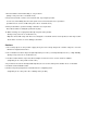
3) Part Names and Functions ■ Body Video output Camera Mounting Base Power(24VAC) Alarm Input Relay output RS-485 DATA Safety Wire Decorative Cover(provided) Dome Anchor Ring Dome Cover Rotate the dome anchor ring to the left to remove it.
Relay Output Cable RS-485 Cable 6 N.C 5 COM2 YELLOW 4 OUT2 BLUE 3 COM1 BLACK 2 OUT1 WHITE 1 N.
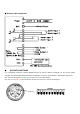
■ Camera cable connection ■ DIP SWITCH SETTINGS In a configuration where the camera’s RS485 data port is used for Camera control(pan, tilt, etc.) by the system controller, the camera’s DIP switches must be configured to specify the camera ID and communication parameters. The camera mounting base needs to be removed to access the DIP switches. See step 1 & 2 on page ? for the information about how to remove the camera mounting base.
■ Camera ID setting The factory default settings of these DIP switches are ID 1 (1-ON,0-OFF) SW1~SW8 DIP SW ID DIP SW ID DIP SW ID 10000000 1 10101000 21 10010100 41 01000000 2 01101000 22 01010100 42 11000000 3 11101000 23 11010100 43 00100000 4 00011000 24 00110100 44 10100000 5 10011000 25 10110100 45 01100000 6 01011000 26 01110100 46 11100000 7 11011000 27 11110100 47 00010000 8 00111000 28 00001100 48 10010000 9 10111000 29 10001100 49 010100
01100010 70 00110110 108 01001001 146 11100010 71 10110110 109 11001001 147 00010010 72 01110110 110 00101001 148 10010010 73 11110110 111 10101001 149 01010010 74 00001110 112 01101001 150 11010010 75 10001110 113 11101001 151 00110010 76 01001110 114 00011001 152 10110010 77 11001110 115 10011001 153 01110010 78 00101110 116 01011001 154 11110010 79 10101110 117 11011001 155 00001010 80 01101110 118 00111001 156 10001010 81 11101110 119
01101101 182 10001011 209 00110111 236 11101101 183 01001011 210 10110111 237 00011101 184 11001011 211 01110111 238 10011101 185 00101011 212 11110111 239 01011101 186 10101011 213 00001111 240 11011101 187 01101011 214 10001111 241 00111101 188 11101011 215 01001111 242 10111101 189 00011011 216 11001111 243 01111101 190 10011011 217 00101111 244 11111101 191 01011011 218 10101111 245 00000011 192 11011011 219 01101111 246 10000011 193 00
4. Installation ■ Preparing the Camera and Decorative Cover for Side Cable Exit The camera and decorative cover should be prepared as shown below when mounting the camera on a ceiling or wall with its cables(power, video output, RS485, alarm in Relay out) exiting from the side. The camera mounting base needs to be removed in order to prepare the camera. See step 1 and 2 below for information about how to remove the camera mounting base.
After loosening the screw, press upwards on the camera and then remove it 2. Rotate the camera base unit in the direction indicated by the arrow and remove it. Step 2 Rotate otate Pull the camera Mounting base Up to remove it 3. To install the camera mounting base to ceiling, attach a template and drill the holes. If you are using the top cable exit configuration, drill the top cable exit part to a template.
4. Affix the camera mounting base onto the ceiling. Use screws(M4) at the locations you marked above to secure the mounting base to the ceiling. Screw Screws (M4, available separately) 5. Attach the safety wire for securing the camera to the mounting base. Pull on the safety wire to make sure its ring is securely connected to the mounting base. Safety Wire Ring NOTE The safety wire is designed to allow the camera to hang from it. Do not apply force greater than the weight of the camera to the wire.
* Is the camera free to looseness? * Does the fixed part of the camera remain in place when you try to rotate it? Rotate Back Camera Mounting Base Camera Camera 9. Separate the two parts of the decorative cover(that comes with camera) Press upwards on the decorative cover at the points marked ■(indicated by the arrows in the illustration below) to unlock the two parts from each other. When removing the decorative cover, the direction to press(←) is shown on the side of the decorative cover.
Back Align Press Press Hook Press 11. In case that the cable exits on the ceiling, fix the decorative cover to the ceiling firmly. In case that the cable exits to the side, align the cutout in the decorative cover with the cable and slide the decorative cover up firmly against the ceiling. Top Cable Exit Configuration Side Cable Exit Configuration Align with cutout ■ Installing the Camera for Outdoor Features * Aluminum body and Polycarbonate Dome Cover.
* Quick and easy to install. * Neat design suitable for interior/exterior decoration Precautions * Note that you need to read carefully all contents related to safety and application methods before application. * Be sure to use the Safety Wire Ring. * Fasten the bracket strong enough to support the camera weight(approx. 5.5Kgs) * The locations for installing the housing should be strong enough to fully secure the accessories, and all installations need to be carried out by experienced engineers.
2. After removing the mounting fix screw(M3), rotate the camera mounting base clockwise to remove it. 3. Fix the camera mounting base to the inside of the outdoor main body with the four screws(M4x8) 4. Attach the wall mount bracket to the wall and run cables. Be sure to line up it with for holes in the wall. 5. After inserting an O-Ring to the outdoor main body, attach the main body to the wall mount bracket with four screws(M4x10) by wrench.
6. After attaching the indoor camera to the camera mounting base, turn and fix it clockwise. And tighten the mounting fix screw with screw driver. 7. Insert the M4 x 10 bolt screws to secure the outdoor dome cover to the outdoor main body.
IP rating IP66 Fan AC24V Operating at over 40°C Heater AC24V/18W Operating at below 4°C Weight 5,500g Dimension(mm) Ø260 x 367(H) 5. Functional Description ■ Setup Menu Overview In this chapter, we will look over the overall structure of the Setup Menu and then look at the functions of each menu .
AREA LEFT → 1~44 AREA RIGHT → 5~48 ATW ATW MODE → ATW/MANUAL/ OUTDOOR/INDOOR MANUAL RED → 0~200 MANUAL BLUE→ 0~200 FOCUS → MANUAL/AUTO/ZOOMTG FOCUS MODE ZOOM TRK MODE→OFF/ON /ZOOM ZOOM TRK SPD →FAST/SLOW AE DIGITAL ZOOM →OFF/ON ZOOM MAG →2X/4X/6X/8X/10X/12X BRIGHTNESS → 0~100 IRIS → AUTO/MANUAL IRIS MANUAL → F1.6 ~CLOSE SHUTTER → ESC/MAN/A.
TOUR BLC → TOUR NO →1~5 TOUR NO DEF → OFF/ NAME → TOURGROUP1 TOUR NAME DEF → OFF/ → 1~120 DWELL TIME SCAN →1~5 SCAN NO SCAN DEFINE → OFF/ON NAME → SCANGROUP1 SCAN NAME DEFINE→OFF/ PAN START POS →<180> PAN END POS →<350> TILT POS →<45> SCAN SPEED →5˚,10˚,15˚,20˚/S PATTERN PATT NUMBER → 1~2 PATT DEFINE → OFF/ON NAME → PATTERN001 PATT NAME DEF →OFF/ PATT RECORD →OFF/ PATT SPEED AUTO RUN OFF/SEQ/TOUR/SCAN/PATT ZONE AREA SEL → 1~8 SET AREA DEFINE →
CAMERA INIT AUTOSEQ INIT PRIVACY ZONE INIT FACTORY INIT System INFO This diagram shown above illustrates the overall structure of the setup menu. In this section, a description of the setup menu features will enable users to tailor it to their personal needs. MAIN MENU 1. PAN TILT SET 2. CAMERA SET 3. AUTOSEQ SET 4. ZONE SET 5. INITIALIZE SET 1. PAN TILT SET 1. ID DISPLAY: /OFF 2. CAM NAME: MAINCAMERA 3. NAME DISPLAY: OFF/ 4. FIRMWARE: ENGLISH 5. DIGITAL FLIP: ON/ OFF 6.
■ DIGITAL FLIP OFF : It operates TILT below 90°. ON : It operates TILT over 90°. ■ FREEZE When you move to Preset, the screen displays the frozen image of the current displayed preset. OFF : It displays the current image. ON : It displays the frozen image. FREEZE works at TOUR in AUTORUN MODE. 1.1. ID DISPLAY ID location can be changed as follows. 1. Select from ID DISPLAY. 2. Press IRIS OPEN KEY.
2. CAMERA SET 1. BACKLIGHT----------OFF//USER 2. MOTION DET 3. ATW ----- ---------------- 4. FOCUS/ZOOM ------ 5. AE ---------------------- 6. DAY&NIGHT --------- 7. SPECIAL -------------- 2.1. BACK LIGHT WDR(for Optical 33x/ 37x zoom only), USER AREA & HLC are selectable.
2.1.2. BLC USER SETUP 1. WINDOW OFF/ON 2. LEVEL LOW/HIGH 3. WINDOW TOP 1~100 4. WINDOW BOTTOM 1~100 5. WINDOW LEFT 1~100 6. WINDOW RIGHT 1~100 Above menu is selectable and adjustable by controller. 2.1.3. HLC LEVEL SETUP 1. HLC LEVEL LOW/HIGH 2. MASK COLOR 0~10 ■ HLC LEVEL Sensitivity is adjustable. ■ MASK COLOR Masking color on the high light is adjustable. 2.2. MOTION DETECT 1. MD NUM : 1~8 2. MD DEFINE : OFF/ON 3. MD DISPLAY : OFF/ON 4. AREA DISPLAY OFF/ON 5.
If the sensitivity gets higher, there is a possibility to have incorrect workings. 1. Motion Detection doesn’t work in SCAN & PATTERN setting. 2. When user uses MD, DWELL TIME should be set over 3 seconds at least in TOUR setting. 3. If there is a shaken lighting directly, do not set the MD because there may be an incorrect working. 4. If there is an instant change for lights which has an effect on the subject, an incorrect working may occurs. 5.
1. FOUCS MODE: 2. ZOOM TRK MODE: MANUAL/AUTO/ZMTRG ON/OFF FAST/SLOW 3. ZOOM TRK SPEED: 4. DIGITAL ZOOM: 5. ZOOM MAG: OFF/ON 2X/4X/6X/8X/10X/12X ■ FOCUS MODE * MANUAL FOCUS is adjustable manually. * AUTO FOCUS is adjustable automatically. * ZMTRG Whenever ZOOM is changed, FOCUS is also readjusted. ■ ZOOM TRK MODE When ZOOM is changed in Wide <-> Tele, user can select if FOCUS will be worked or not. It is applied only to AUTO and ZOOM TRK mode.
■ BRIGHTNESS : Brightness on the screen is adjustable. ■ IRIS The brightness on the screen can be adjustable depending on the amount of light through exposure meter. AUTO : The exposure meter is adjusted automatically. MANUAL : User can adjust the exposure meter manually to optimize the brightness on the screen. ■ SHUTTER When capturing a subject, moving fast or under low light condition, user can adjust the shutter speed to faster or slower to get improved images.
4.DURATION: FAST/SLOW 5. FILTER DELAY: 5/7/10/15/20/30/40/60SEC B/W mode with removed IR cut filter offers crystallized clear image under low light condition. On the contrary, Color mode with replaced IR cut filter works at daytime. ■ D/N MODE AUTO : Color mode at daytime and B/W mode at nighttime. It is switchable automatically according to the designated lux condition. ■ BURST MODE OFF : BURST signal is removed. ON : BURST signal is output with together B/W Luminance signal.
■ SHARPNESS Overall sharpness on the screen is adjustable. ■ COLOR Overall color density on the screen is adjustable. 3. AUTOSEQ SET 1. PRESET 2. TOUR 3. SCAN 4. PATTERN 5. AUTORUN OFF/SEQ/TOUR/SCAN/PATT Menu Shift : UP, DOWN, LEFT, RIGHT KEY Menu Open : IRIS OPEN KEY Menu Close : IRIS CLOSE KEY PRESET : Location of the current PAN/TILT and ZOOM can be programmed. In ALARM or TOUR operation, the camera moves to the programmed preset.
Menu Close : IRIS CLOSE KEY ■ PRESET NO Total 128 presets can be set up. Change of PRESET NO is done by LEFT and RIGHT KEY. ■ PRESET DEFINE OFF : PRESET doesn’t work ON : Applicable PRESET is workable. Location change of PAN/TILT/ZOOM in PRESET is as follows. 1. After PRESET DEFINE is changed from OFF to ON, press IRIS OPEN KEY 2. Locate PAN/TILT to the desirable place. PREST NAME: PRESET0001 PAN: TILT: XXX XXX ZOOM: T/W EXIT: IRIS CLOSE 3.
1. When setting PRESET by the shortcut key, PRESET can be set in No.1-No.64 and, regarding over No.65, it should be set up by OSD Menu. 2. Default set up value of BRIGHT, BLC and ATW in PRESET is decided by Factory Default. 3.2. TOUR This function is to repeatedly operate Group Surveillance with programmed presets. 1. TOUR NO: 1~5 2. TOUR NO DEF: OFF/ 3. NAME: TOURGROUP1 OFF/ 4. TOUR NAME DEF: 5. DWELL TIME: 1~120 ■ TOUR NO Maximum 5 groups can be registered.
■ DWELL TIME It is a waiting time between PRESET execution and next PRESET. 1. If TOUR GOURP1 PRESET is set up as follows. 1. PRESET NUMBER 1 2. PRESET NUMBER 2 3. PRESET NUMBER 3 4. PRESET NUMBER OFF 5. PRESET NUMBER 4 After operating as PRESET1 -> PRESET2 -> PRESET3, it is returned to PRESET1. Namely, if there is “OFF” during the operation in serial order, it is returned to the first preset 3.3.
How to change is as follows. 1. After changing SCAN NAME DEF from OFF to , press IRIS OPEN KEY. 2. How to change the SCAN name is the same as “1.2 CAMERA NAME DISPLAY”. ■ PAN START POS It sets up the initialized location of SCAN. Controllable angle is 0~ 360° , 0 ~ -360°. How to set up is as follows. 1. Press IRIS OPEN KEY in PAN START POS. PAN START POSITION SET PAN START POSITION: XXX EXIT: IRIS CLOSE PAN Shift : LEFT, RIGHT KEY 2. After shifting to a desirable position, press IRIS OPEN KEY.
MENU Shift : UP, DOWN, LEFT, RIGHT KEY MENU Open : IRIS OPEN KEY MENU Close : IRIS CLOSE KEY ■ PATT DEFINE OFF : PATTERN is cancelled ON : PATTERN is set up. If operating it in AUTO RUN, PATT DEFINE should to be ON. ■ NAME It changes PATTERN Name.. How to set up is as follows.. 1. After changing PATTERN NAME DEF from OFF to , press IRIS OPEN KEY. 2. How to change the name is the same as “1.2 CAMERA NAME DISPLAY”. ■ PATT RECORD OFF : ON PATTERN is not memorized. : PATTERN is momorized.
4.TOP/BOTTOM-1 XXX 5.TOP/BOTTOM-2 XXX 6.LEFT/RIGHT-1 XXX 7.LEFT/RIGHT-2 XXX MENU Shift : UP, DOWN, LEFT, RIGHT KEY MENU Open : IRIS OPEN KEY MENU Close : IRIS CLOSE KEY ■ AREA SEL Up to 8 PRIVACY AREAs can be set up. ■ AREA DEFINE OFF : PRIVACY ZONE is not activated.. ON : PRIVACY ZONE is activated. ■ AREA NEW SET OFF : Previous PRVIACY ZONE is activated. ON : New PRIVACY ZONE is set up from the current PAN/TILT position.
MENU Close : IRIS CLOSE KEY ■ POWER ON RESET The unit is initialized. ■ PAN/TILT INIT 1. PAN/TILT MENU is initialized. 2. PAN/TILT location is initialized. ■ CAMERA INIT Only CAMERA setting menu is initialized.. ■ AUTO SEQ INIT 1. Only AUTO SEQ menu is initialized. 2. Setting angle of PRESET and Memory of PATTERN are not initialized. ■ PRIVACY ZONE INIT PRIVACY ZONE is initialized. ■ FACTORY INIT All set ups are initialized as a factory default. .
be set up by OSD Menu. ※ WTX-1200A – Simple PRESET Shift ※ It works when OSD MENU is not activated. Press F1 key shortly after pressing RRESET number. And then, it moves to the corresponding PRESET. However, it is valid only up to PRESET no. 32 of which PRESET DEFINE is set to ON. ※WTX-1200A - Simple TOUR operation※ It works when OSD MENU is not activated Press F1 key shortly after pressing Keypad No. 71. It works when TOUR DEFINE is ON and TOUR related MENU is set up properly.
※ WTX-1200A - Simple Sequency operation ※ It works when OSD MENU is not activated Press F1 key shortly after pressing Keypad No. 70. It works when PRESET is set up. ※ Quick Operation Key Table ※ [PELCO D /P PROTOCOLS] Number 1~64+Preset Function Setting Preset Press Preset button over 2 seconds. 1~64+Preset Executing Preset 66+Preset Executing Scan 70+Preset Executing Sequency 71+Preset Executing Tour 81+Preset Executing Pattern 95+Preset IRIS OPEN (OSD Menu ) 96+Preset IRIS CLOSE 6.
Outdoor 7. Specification Model 27x/ 33x/ 37x Speed Domes Image sensor 1/4” Super HAD CCD(27x)/ Color Vertical Double Density CCD(33x, 37x) Effective Pixels NTSC : 768(H) x 494(V), PAL : 752(H) x 582(V) H. Resolutions 550TVL(Color)/ 680TVL(B/W) Synchronizing system Internal Scanning system 2:1 Interlaced Video output VBS : 1.0Vp-p Composit, 75 ohms S/N Ratio More than 50dB(AGC off) Min. illumination 0.7Lux/F1.6(Color), 0.0002Lux(Sens-ups, x256), 0.06Lux/F1.
Gain Control Low/ Middle/ High/ Off Sens-up On/ Off(2x ~ 256x) 3D Noise Filter Low/ Middle/ High/ Off Privacy On/ Off(8 Programmable zones) Preset 256 Points Digital Flip On/ Off Focus control Auto/ Manual/ One Push Iris control Auto/ Manual Motion Detection On/ Off(Built-in Alarm output connector) Protocol RS-485(PELCO-D/P) Power Source 24VAC Operating current 20W Max. Lens Auto Focus Digital zoom Zoom ratio Angle of view 37x F3.5~129.5mm(F1.6) 33x F3.5~115.5mm(F1.