1814 South Election Rd., Suite 200, Draper, UT 84020 (801) 495-2310 FAX (801) 495-2255 Radiological Security Program Wireless Optic Fiber Seal WOFS Installation Guide V029627_02_WOFS_Installation_Guide.
11814 South Election Rd., Suite 200, Draper, UT 84020 (801) 495-2310 FAX (801) 495-2255 Table of Contents 1 Introduction .............................................................................................................................. 3 2 Concept of Operation ................................................................................................................ 3 3 Installation of the WOFS Receiver Hardware......................................................................
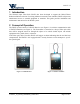
2015-07-31 1 Introduction The Wireless Optic Fiber Seal (WOFS) has been developed to support the Global Threat Reduction Initiative mission of securing radioactive material. Once installed, WOFS will prevent unmonitored access to essential equipment or materials. This guide provides installation and maintenance instructions for the WOFS system. 2 Concept of Operation The WOFS system consists of a WOFS Receiver (see Figure 1) in wireless communication with a WOFS Transmitter (see Figure 2).
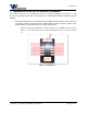
2015-07-31 3 Installation of the WOFS Receiver Hardware The WOFS Receiver can communicate with up to eight Transmitters (see Figure 3). The Receiver is typically connected to an alarm panel or to the Integrated Remote Monitoring System (iRMS). When the WOFS Receiver is integrated with an iRMS, WOFS supports a user interface at an operator security station that shows WOFS health, location of alarm, camera video, and the iRMS can send email and text message notifications.
2015-07-31 Connecting Power The Receiver is powered by +12 VDC supplied by the facility where the Receiver is installed. 1. Connect power to the terminals by removing the 4 recessed, Phillips-head screws and open the case to access the terminal blocks. 2. Turn off the source of the facility’s +12VDC. 3. Connect +12 VDC wire and ground wire to Receiver’s DC Power terminals.
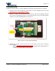
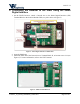
2015-07-31 4 Connecting the Receiver to the iRMS Using the Smart Digital Interface 1. On the WOFS Receiver, attach a Ground wire to the Smart Digital Interface (SDI) Terminal Block to the location labeled GND (see yellow boxes in Figure 5). Figure 5 - Smart Digital Interface terminal block 2. Open the iRMS unit. 3. Attach the other end of the Ground wire to Terminal Block J8, at location screw #14 (see Figure 6). For more information, refer to the CHCT manual.
2015-07-31 4. On the WOFS Receiver, attach the Receiver wire to the Smart Interface Terminal Block to the location labeled RX (see previous Figure 5). 5. Attach the other end of the Receiver wire to the iRMS Terminal Block J8, at screw #13 (see previous Figure 6). 6. On the WOFS Receiver, attach the Transmitter wire to the Smart Interface Terminal Block to the location labeled TX (see previous Figure 5). 7.
2015-07-31 o Use the terminal jacks that are either Normally Open (N/O) or Normally Closed (N/C), depending on the configuration of the alarm panel (see section 7 of this manual for more information on the N/O or N/C requirements). 2. Route the wires from the Receiver terminal block through the hole next to the SMA antenna connector (see previous Figure 8). 8. Use the zip tie to secure the wires in order to reduce the strain on the terminal block wires (see previous Figure 8). 9.
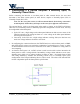
2015-07-31 7 Determining if a Device Requires a Normally Open, or Normally Closed State Before connecting the Receiver to an alarm panel or other external device, the user must determine if the alarm system panel (or other device) requires a Normally Open (N/O) or Normally Closed (N/C) state. Note: For the rest of this section, it will be assumed that the device being connected is an alarm panel, but the theory and steps are the same for a different external device.
2015-07-31 Figure 9 - Normally Open configuration Figure 10 - Normally Closed configuration V029627_02_WOFS_Installation_Guide.
2015-07-31 8 Installation of the WOFS Transmitter Hardware Installation of the WOFS Transmitter Hardware requires three steps: Installation of the batteries Mounting the Transmitter to a secured surface Setting up the Fiber Optic Loop The WOFS Transmitter is powered by 2 AA-sized batteries. The battery power level is monitored by the WOFS Receiver. The Transmitter uses a fiber optic cable to wrap around (or through) the object to be sealed.
2015-07-31 9 Installing or Changing Transmitter Batteries Before mounting the Transmitter to a wall or secured surface, install 2 AA-sized alkaline batteries using the steps below: 1. Remove the 4 recessed, Phillips-head screws and open the Transmitter case to access the battery compartment (see Figure 13). o Remove the old batteries, if applicable. 2. Insert 2 AA-sized alkaline batteries matching the polarity pictured in the battery holder (see Figure 14). 3.
2015-07-31 10 Mounting Transmitter on Wall or Secured Surface Before the WOFS unit is mounted to a secured surface, the user should have determined how the fiber optic loop is going to be secured around the device to be monitored. Ensure that the fiber loop surrounding the protected asset can be securely wrapped around the section necessary to protect, and still reach the WOFS fiber optical cable terminals.
2015-07-31 2. Peel the paper off one side of the mounting tape. 3. Press the mounting strip onto the back of the Transmitter, making sure to line up the TID hole on the WOFS unit with the hole in the mounting tape (see Figure 18). 4. Peel the paper from the second side of the mounting tape. 5. Press the WOFS unit onto the pre-determined, secured surface.
2015-07-31 2. Insert one end of the fiber optic cable into the Transmitter screw terminal until fully seated (see Figure 20). 3. Turn the screw terminal clockwise to secure the cable (see Figure 21). Secure the protected object (i.e. radioactive material container) with the optic fiber cable, and then secure other end of the fiber optic loop into the other screw terminal. Either end of the fiber optic loop can be installed in either screw terminal.
2015-07-31 12 Pairing a WOFS Transmitter to a WOFS Receiver A Transmitter needs to be paired to a Receiver only once, at the time of installation. The pair will remain paired thereafter, even after power loss, or during battery replacement. One Receiver can be paired with (and can monitor) up to 8 Transmitters. To pair a Transmitter and Receiver: 1. On the Receiver, press and hold the pairing button for 3 seconds. The status LED will start flashing blue indicating “discovery” mode. 2.
2015-07-31 13 Unpairing a WOFS Transmitter to a WOFS Receiver On occasion, the need may arise to unpair a transmitter from its paired receiver. This can be necessitated when any of the following happens: A Transmitter may need to be moved to a different location, and paired with a different Receiver. A transmitter may not be functioning correctly, and the user may choose to replace one Transmitter with another. A Receiver may not be functioning properly, and it will be replaced.
2015-07-31 14 Receiver Status Lights The Receiver’s Status light is on at all times (after correct installation). Any Receiver that has been paired with a Transmitter will also have its Transmitter Status lights constantly showing for each paired set. The Status of a Transmitter paired to the first location on the Receiver is indicated by the LED labeled 1, the Transmitter paired to the second location is shown by the LED labeled 2, and so on. LED lights for unused pairs will remain off (see Figure 22).
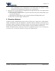
2015-07-31 15 Transmitter Status Lights and Checking Transmitter Status The Transmitter is designed with a Status Button and an LED light to indicate the Transmitter’s status (see Figure 23). If the Transmitter has been paired with Receiver (and is within range) the Status button on the Transmitter can be pressed at any time to check the Transmitter’s status, lighting up the LED.
15-07-31 16 Regulatory Compliance FCC Declaration of Conformance This device complies with part 15 of the FCC rules. Operation is subject to the following two conditions: (1) This device may not cause harmful interference, and (2) this device must accept any interference received, including interference that may cause undesired operation. Any changes or modifications not expressly approved by manufacturer could void the user’s authority to operate the equipment.