
User's Manual

2015-07-31
V029627_02_WOFS_Installation_Guide.docx Page 7 of 20
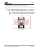
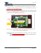
4. On the WOFS Receiver, attach the Receiver wire to the Smart Interface Terminal Block
to the location labeled RX (see previous Figure 5).
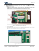
5. Attach the other end of the Receiver wire to the iRMS Terminal Block J8, at screw #13
(see previous Figure 6).
6. On the WOFS Receiver, attach the Transmitter wire to the Smart Interface Terminal
Block to the location labeled TX (see previous Figure 5).
7. Attach the other end of the Receiver wire to the iRMS Terminal Block J8, at screw #12
(see Figure previous 6).
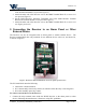
5 Connecting the Receiver to an Alarm Panel or Other
External Device
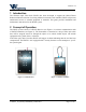
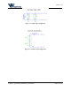
The Receiver can also be integrated with an alarm panel or another external device. The
Receiver terminal block has relay terminals for two different devices (device A, and device B),
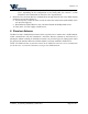
as shown in Figure 8.
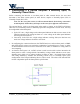
Figure 7 - Receiver's main terminal block, wire access point, zip tie for wires
The PC board labels mean the following:
COM is the common terminal.
NC is the normally closed relay contact (for instances when the relay is not energized).
NO is the normally open relay contact.
To connect external devices to the Receiver:
1. Connect the relay terminal wires inside the WOFS Receiver to the alarm panel (or other
device), following the manufacturer’s directions, using NEC guidelines.