Front View 2 & 4 DRIVE USER GUIDE Users Manual Page 1 of 57
Front View 2 & 4 DRIVE USER GUIDE Technical Support Visionman Computers, Inc. 3200 N. San Marcos Place Chandler, AZ 85225 Telephone: 1-800-690-6771 extension 2665 Support e-mail: support@visionman.com For additional information, please visit the Visionman Web site: www.visionman.com Copyright © 2008 Visionman.com. All Rights Reserved.
Front View 2 & 4 DRIVE USER GUIDE Introduction _____________________________________________________________________________ 4 Front View ____________________________________________________________________________________4 Rear View _____________________________________________________________________________________5 System Setup _____________________________________________________________________________ 6 Connecting the Storango SCM200/SCM400 to the Network __________________________________________
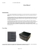
Front View 2 & 4 DRIVE USER GUIDE Users Manual Introduction The Storango SCM200/SCM400 storage appliance is a powerful and feature-rich system designed as a flexible solution for storing and sharing your digital files across a home or office network or across the Internet. The SCM200/SCM400 makes remote management a simple task with its Web-based user interface.
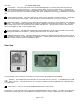
Rear View 2 & 4 DRIVE USER GUIDE Power Button: Press the power button to turn the SCM200/SCM400 on. The Green LED under the button will indicate that the system is powered on. Press and hold the button to power the system down. If the LED is off, then it indicates that either the system is still initializing or the system is not powered on. A blinking LED indicates either the system is rebooting or the RAID is rebuilding, and will be unavailable for file sharing or administration during this time.
Connecting the Storango SCM200/SCM400 to the Network 2 & 4 DRIVE USER GUIDE Power Connector: Use this port to connect power to the SCM200/SCM400. The SCM400 uses a standard computer type AC power cord, whereas the SCM200 uses an AC to DC power adapter. System Setup This section gives instructions on how to setup the Storango SCM200/SCM400.
Logging into the SCM200/SCM400 configuration utility 2 & 4 DRIVE USER GUIDE Turning the System Off To power down the system, press and hold the power button down for about five seconds. The green power LED will turn off, indicating that a shutdown is in progress. The shutdown process will start and take about 10 to 15 seconds to complete. When the other LED’s have turned off, the system is off. Resetting the System The storage solution has a reset button in the back.
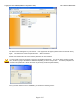
Logging into the SCM200/SCM400 configuration utility 2 & 4 DRIVE USER GUIDE The above screen will appear on your browser. If the page does not appear, please wait a few minutes and try again. The default user name and password are: admin and admin Please note that both the user name and the password are case sensitive. In some cases it may be necessary to open the configuration file directly.
System Configuration 2 & 4 DRIVE USER GUIDE Open the configuration folder by double-clicking on that folder’s icon. Once inside this folder, open the Index file by double-clicking its icon. This will bring you to the configuration login screen in the same way as typing the IP address or name directly into your browser. System Configuration The web screen will now show the display below. configuration.
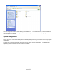
System Configuration 2 & 4 DRIVE USER GUIDE On the top right corner are four Icons choices: , that can be selected for some more detailed configuration The above is a simplified screen for set up and configuration. setup. The choices are self explanatory for configuration and icon from the top right corner. This will take you to the To get to more detailed configuration screens, select following configuration screen, with more detailed choices. Clicking it again will simplify your choices.
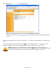
System Configuration 2 & 4 DRIVE USER GUIDE General Setup Screen This screen allows you to configure the basic information about the SCM200/SCM400 storage appliance, such as give a name and brief description for the machine, select the web GUI protocol, and set the time zone for your storage device. You can also set the date and time or enable automatic time synchronization via NTP (Network Time Protocol) Service. You have to specify the IP address of the NTP servers from which you want to synchronize.
System Configuration 2 & 4 DRIVE USER GUIDE Alerts Setup In the Alerts setup screen, you can configure the system to automatically send e-mails or pop-up messages for event notification, to the administrator to monitor the functionality of the storage device. These messages can be warnings or errors related to Fan, temperature, Hard Drive functionality, Volume, Network, USB, Users and Groups.
System Configuration 2 & 4 DRIVE USER GUIDE Change Admin Password Change the administrator password: Enter the old password. Enter the new password. The maximum length of the password must not be more than 15 alphanumeric characters. Password is case sensitive and should be entered exactly in the same way each time. Re-enter the new password. Click Submit.
System Configuration 2 & 4 DRIVE USER GUIDE Firmware Update This screen provides information about the current firmware version and allows you to perform a firmware upgrade. Check on our web site to see if a newer version of the firmware is available. To upgrade the firmware: Download a copy of the new firmware from our Website to your computer. The firmware image filename should have the following format: .IMG; for example SCM200_V0_1_6.IMG.
System Configuration 2 & 4 DRIVE USER GUIDE Printer Management The Printer Management screen allows you to manage the USB printers connected to the storage device, as well as manage print queues and print jobs across the network. Install the printer drivers on the PC’s that will use this printer. For Windows: Connect the USB printer to the storage device.
System Configuration 2 & 4 DRIVE USER GUIDE Configuration Management Configuration Management screen allows administrators to easily perform backup or restore operation of the storage systems settings or revert system to factory default settings. To backup your current configuration settings: On the Configuration Management page, click Configuration Download. Click Open and specify a file name and location where you want to save the file and select save.
System Configuration 2 & 4 DRIVE USER GUIDE Performing a factory default reset will erase all settings in SCM200/SCM400. System settings such as the IP address, machine name, admin user name, password, RAID reconstructs, and media files stored in SCM200/SCM400 are lost. On the Configuration Management page, click Factory Default Restore and click OK. It is important to backup all critical data and files before undertaking any restore operations.
System Configuration 2 & 4 DRIVE USER GUIDE Advanced Setup This screen allows you to configure the system identification LED, setup a system for a secure connection by generating an SSL (Secure Sockets Layer) certificate and a key, and perform a reboot or shutdown for the SCM200/SCM400. To turn on the system identification LED: Click the Turn LED ON button to enable the system identification LED, and select Submit.
System Configuration 2 & 4 DRIVE USER GUIDE By default, your storage system will place the installed disks in what is called a “span” configuration. This utilizes all available disk space for networked storage. If your storage system does not have all the disk slots used you may want to add more capacity later. If that is the case, you may want to enable the storage system’s “Extend” mode. Click on the drop down menu and select “Enabled” and then click on Submit.
System Configuration 2 & 4 DRIVE USER GUIDE Network: LAN Setup Screen This screen allows access to all network configuration options; such as setting the connection method, changing the IP address, netmask, gateway, DNS (Domain Name Service) server IP address, and the ability to configure the optional jumbo frame size. DHCP is the default network IP setting for the storage device.
System Configuration 2 & 4 DRIVE USER GUIDE In the MTU Size (Bytes) box, enter the appropriate MTU size. Click Submit. You must restart the system for these changes to take effect.
System Configuration 2 & 4 DRIVE USER GUIDE Network: Services The Network services screen allows you to set up and manage file services for different types of clients, such as Mac, Windows, Linux, Unix, on your network using the FTP (File Transfer Protocol) or NFS (Network File System) protocols. Computers can access files and shared folders on your storage system, without requiring any special software.
System Configuration 2 & 4 DRIVE USER GUIDE To enable the NFS file service on SCM200/SCM400: On the Services page, click the NFS service Enable checkbox. The IP Allowed box appears. Enter the IP filters that are allowed for NFS service, then click Add to add the new IP filter, and select Submit.
System Configuration 2 & 4 DRIVE USER GUIDE Workgroup/Domain Setup This screen allows you to setup the storage system as a workgroup or domain member. Both workgroup and domain are ways of grouping computers on the network. By default, the storage system is set as a Workgroup. Unlike workgroups, domains are controlled from a central location (domain controller) and require central authentication before you can join them. Workgroups, in contrast, are much simpler to control.
System Configuration 2 & 4 DRIVE USER GUIDE Domain Name, Administrator and Administrator Password for the authorization. To join a domain as a member: Select the Domain Member button. In the Domain Name box, enter the domain name. In the Domain Controller IP Address box, enter the domain controller’s IP address. In the Administrator box, enter the administrator’s user name. In the Administrator Password box, enter the administrator’s password. Click Submit.
2 & 4 DRIVE USER GUIDE Storage Screens The Storage screens provide all the necessary options required for individual storage disk configuration and maintenance. You can also change RAID configuration, set shared folder names, format and disconnect USB hard drives that are connected to the system. The above screen shows a screen shot from the SCM200, which has two drives. The SCM400 screens will actually show up to four drives, and different RAID configurations.
Storage Screens 2 & 4 DRIVE USER GUIDE Volume Management The Manage Volume tab contains a table that shows all volumes currently defined on the SCM200/SCM400’s hard drives and provides access to configuration details relating to how the disks are partitioned and how RAID volumes are created on these partitions. These volumes are the ones used for creating shares.
Storage Screens 2 & 4 DRIVE USER GUIDE Degraded - A drive is missing or contains corrupted data for the existing volume. Recovering - Occurs when the system detects a spare drive that was inserted into a degraded RAID volume.
Storage Screens 2 & 4 DRIVE USER GUIDE WARNING: CHANGING THE RAID TYPE WILL ERASE ALL DATA. BEFORE CHANGING THE RAID SETTINGS. PLEASE BACKUP YOUR FILES Manage RAID The Manage RAID screen allows you to configure the SATA hard drives into different RAID types. RAID (Redundant Array of Independent Disk Drives) refers to an array of multiple independent hard drives that provide high performance and reliability. RAID function depends on the number of drives present and the RAID level you selected.
Storage Screens 2 & 4 DRIVE USER GUIDE Default RAID configuration - The default RAID configuration for each hard drive installed on SCM200 is as follows: • If one drive is installed to an empty drive bay, the default RAID configuration is mirror and the volume status is degraded. • If system has one hard drive and a new hard drive is added, the default RAID configuration is mirror and the volume status is good.
Storage Screens 2 & 4 DRIVE USER GUIDE Default RAID configuration: follows: • • • The default RAID configuration for each hard drive installed on SCM400 is as If one drive is installed to an empty drive bay, the default RAID configuration is mirror and the volume status is degrade. If system has one hard drive and a new hard drive is added, the default RAID configuration is mirror and the volume status is good. If two or more hard drives are installed, the default RAID configuration is span.
Storage Screens 2 & 4 DRIVE USER GUIDE Share Management This screen provides access to configuration details relating to how shares are made available by the SCM200/SCM400. This menu contains a table that shows all the shares, logical volumes, and protocols currently defined on the SCM200/SCM400 system. SCM200/SCM400 comes preconfigured with four shared folders: download, media_library, public, and private.
Storage Screens 2 & 4 DRIVE USER GUIDE To create a new share on a logical volume: Click on the Create icon Assign a share name. The share name can contain up to 32 characters, including alphabetic, numeric, or underscore. Enter a brief description, if desired. Select file sharing protocol. The SCM200/SCM400 supports the following file sharing protocols: CIFS (Common Internet File System) - A standard way that clients share files across intranets.
Storage Screens 2 & 4 DRIVE USER GUIDE Using NFS protocol, the client can access all or a portion of the shared file directory on the network. The portion of the file directory can be accessed with the privileges (read only or full access) designated to each file. Click Submit. NOTE: If you have “Setup access control after creating share” checked, you will be taken directly to the Access Control for this share and you can assign users or make the share public for your network.
Storage Screens 2 & 4 DRIVE USER GUIDE USB Management The Storage Appliance supports USB external hard disk drives and USB Flash drives. CD/DVD/CDRW/DVDRW Drives. To format a USB hard drive: partitions, volumes…etc.) It does not support USB (Remember, formatting a drive erases all data from the drive, including any Connect a USB hard drive to SCM200/SCM400. On the USB Management page, select the USB Disk tab. Select the USB hard drive you want to format and click the Format icon.
Storage Screens 2 & 4 DRIVE USER GUIDE USB Backup USB port number one, which is next to the Ethernet port on the SCM200 and on the front for the SCM400, has been configured to handle the automatic backup of the contents of a USB drive attached to the SCM200/SCM400. You can use the other USB port(s) for transferring data to and from the storage system, but only USB port one can be used for automatic backup.
Access Control Section 2 & 4 DRIVE USER GUIDE Access Control Section The Access Control screens allow you to configure access to files and folder in the Storage Appliance. User Management The User Management screen allows the system administrator to create, edit, and delete user accounts on the system. Administrators can create Public or Private user accounts and further customize these accounts with privilege levels. To create a user account: Click the Create icon.
Access Control Section 2 & 4 DRIVE USER GUIDE In the User name box, enter the user name. Click the Grant Administration Rights checkbox to allow user to have administrative rights and to access and configure the System Configuration Utility. In the Full Name box, enter the user’s full name. To secure the shared folder so that users must use a password to access it, enter a password in the Password box.
Access Control Section 2 & 4 DRIVE USER GUIDE The above screen shows the new user has been added successfully. To modify a user account: Select the user account you want to modify. Click the Modify icon.
Access Control Section 2 & 4 DRIVE USER GUIDE Make the changes you want, then click Submit. To delete a user: Select the user account you want to delete. Click the Delete icon. You will get a warning about deleting of the user. Click on OK, and the user will be deleted. Group Management The Group Management submenu allows administrators to create, edit, and delete a group of users on the system.
Access Control Section 2 & 4 DRIVE USER GUIDE To create a new local group: Click the Create icon.
Access Control Section 2 & 4 DRIVE USER GUIDE Assign a new group name for the new group. As before, the name can be up to 32 characters long. Enter a description for the new group. In the User List, add the users that you want to have access to the group. And Click Submit. The following screen will show up to confirm that you have successfully created a new group.
Access Control Section 2 & 4 DRIVE USER GUIDE To modify a local group: Select the group you want to modify. Click the Modify icon.
Access Control Section 2 & 4 DRIVE USER GUIDE Make the changes you want, and then click Submit. To delete a local group: Select the group you want to delete. Click the Delete icon. You will get a warning to confirm the deletion of the user group. Share Access The Share Access screen allows administrators to set the access control for each user or group in the Access list. Each user or group defined in User Management must have an assigned privilege level for every shared folder on the storage appliance.
Access Control Section 2 & 4 DRIVE USER GUIDE No Access has the highest priority. Read Write + Read Only = Full Access. If the access control is assigned to a user or group, the full access, read only, and no access icons appear on the Share Access page. You can move your mouse over the icon to view the user or group list. To assign privilege levels for users or groups: Select a user or group, then click the Edit icon.
Access Control Section 2 & 4 DRIVE USER GUIDE The upper section of the page contains an information table that lists the share folder’s logical volume name and supported file service protocol. Each defined user or group must have a privilege level for every shared folder you create. Click the Enable Public Access checkbox if you want to enable any user or group to have access to the shared folder. In NFS Access, you can set a privilege level for a Linux or Unix client.
Access Control Section 2 & 4 DRIVE USER GUIDE When there is a conflict in the access rights of the user and group, SCM200/SCM400 uses the following rule to handle the conflict: No Access has the highest priority. Read Write + Read Only = Full Access. If the access control is set, a small icon appears on User/Group permission box, the administrator can move the mouse cursor over the icon to see the user/group list.
Access Control Section 2 & 4 DRIVE USER GUIDE Enable the Media Server by selecting the Enable button. You can also decide if you want the media files sorted in alphabetical order or by the date the file was created. Select Submit, for the system to sort the media content in the system and save your changes.
Access Control Section 2 & 4 DRIVE USER GUIDE The above screen will show that media content in the storage system has been identified and sorted.
Access Control Section 2 & 4 DRIVE USER GUIDE Enable the iTunes Server by selecting the Enable button. Select Submit, for the system to save your changes. You will then see the server appear in the shared area on your iTunes application. Any songs you have transferred to the media_library will automatically appear when you click on the server name. A server named “S3M” has been configured in the following example.
Using the Status Menu 2 & 4 DRIVE USER GUIDE The above screen will show that media content in the storage system has been identified and sorted. Using the Status Menu The Status menu displays general information about the system, such as machine name, firmware version, current date/time, machine up-time, and volume of the storage space that is being used.
Using the Status Menu 2 & 4 DRIVE USER GUIDE Logs Logs screen includes five tabs — System, CIFS, FTP, Printer, Settings. It displays a record of activity that has occurred on storage device. Each activity displays a time and date associated with the event and a description of the activity that took place. Settings Tab In the settings tab, you can decide the sequence that the log should be showed and the size of the log.
Using the Status Menu 2 & 4 DRIVE USER GUIDE The above is an example of the display from the system logs screen. The System Logs records significant problems that occur in the system. You can obtain information from the following conditions or errors that may occur in the system components, hardware or software components.
Using the Status Menu 2 & 4 DRIVE USER GUIDE The CIFS, FTP and Printer tabs track the logs for their respective functions. CIFS The CIFS (Common Internet File System) tab displays the file and print services log of CIFS clients. FTP The FTP (File Transfer Protocol) tab displays file transfer sessions to and from the SCM200/SCM400. Printer The Printer tab displays the print services log.
Product Support 2 & 4 DRIVE USER GUIDE Product Support To get the latest firmware, please visit Visionman.com web site to find the latest firmware version, and instructions on how to download and update the firmware on your Storango SCM200/SCM400. Troubleshooting For any issue, first ensure that you are using the latest firmware for the Storango SCM200/SCM400. resolve your server problems on your own, contact your dealer or Storango for assistance.
Technical Specifications 2 & 4 DRIVE USER GUIDE From the Internet Explorer menu, go to Tools, then select Internet Options. Choose the Security tab, then click Custom Level. Scroll down to Active Scripting, then select Enable. Click OK. To enable JavaScript in Mozilla Firefox 1.0: From the Mozilla Firefox browser, select Tools. Click Options, then select Web Features. Select the Enable JavaScript check box, then click OK. To enable JavaScript in Mozilla Firefox 1.
Technical Specifications 2 & 4 DRIVE USER GUIDE 16 MB flash ROM for firmware storage Storage Capacity 320 GBs - 2 TBs Hard Drives Supported 3.5” SATA II 7200 RPM Hard Drive Buffer Size 8 MB cache and above RAID Constructs RAID 0 (Stripe), 1 (Mirror), 5 (Parity), Linear (Span) USB interface 3 (SCM400) and 2 (SCM200) x USB 2.