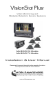
VisionStat Plus ® Video Monitoring and Obstacle Detection Sensor Systems MA-BCKS-5.6 Models MA-BCKS-7.0 Models Installation & User Manual Please read this manual thoroughly before operating the device and keep this document for future reference www.mobileawareness.
Mobile Awareness MOBILE AWARENESS, LLC MobileTRAQ™ , SenseStat®, TireStat®, VisionStat® MANUFACTURER’S LIMITED WARRANTY Three Year Limited Warranty Effective January 1st, 2014 Subject to the limitations and exclusions set forth in this Limited Warranty, MobileTRAQ™, SenseStat®, TireStat®, VisionStat® (herein collectively called the “Product”) is warranted by Mobile Awareness, LLC (the “Manufacturer”) against defects in material or workmanship that result in product failure during the three-year period fol
VisionStat Plus Video Monitoring and Obstacle Detection Sensor System Contents of Manual 1. 2. 3. 4. 5. 6. 7. 8. 9. 10. 11. 12. 13. Product Overview, Product Features, Product Specifications………………..….….……….....………...5 VisionStat Plus Package Contents, Optional Items and Accessories........……….………………..........7 About the Monitor..................................................................................................................................8 About the Cameras................................
Mobile Awareness Storage and Keeping 1. 2. 3. 4. 5. 6. 7. 8. 9. Do not expose the Monitor, Cameras or other equipment to excessive heat or cold. Please read and follow the technical specifications provided in this manual. Never use the device near a bathtub, wash basin, kitchen, damp basement, swimming pool or similar places. Never use the device in environments with excessive moisture, dust or smoke. Avoid dropping or striking the device.
VisionStat Plus Video Monitoring and Obstacle Detection Sensor System Product Overview VisionStat Plus is an innovative version of the VisionStat Video Monitoring System integrated with a SenseStat® Obstacle Detection Sensor System. This leading-edge technology allows the real-time Sensor distance and zone information to be displayed, along with the camera image, on a single color video monitor.
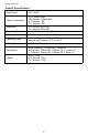
Mobile Awareness Product Specifications Power Input 10~32VDC Power Consumption ECU: 200mA Max LED Monitor: 250mA Max 5.6” Monitor: ~5W 7.0” Monitor: ~6W Resolution 5.6” Monitor: 640 x 480 7.0” Monitor: 800 x 480 Distance Detection 0.72~8.20 (ft) / 0.22~2.5 (M) Detection Tolerance +/- 0.8 inches / +/- 0.02M (at 25°C ) Operating Temp ECU and Sensors: -30°C to +75°C Monitor and Camera: -20°C to +70°C Storage Temp -30°C to +80°C Dimensions ECU: 110mm (L) x 92mm (W) x 32mm (H) 5.
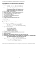
VisionStat Plus Video Monitoring and Obstacle Detection Sensor System VisionStat Plus Package Contents (Hardware) Monitor 5.6” Wired Monitor (P/N: MA-LCDS-5.6) 7.0” Wired Monitor (P/N: MA-LCDS-7.
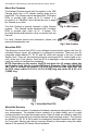
Mobile Awareness About the Monitor The VisionStat Plus Monitor is a colored TFT LCD Monitor with a wide angle view and a high resolution display. It supports both PAL and NTSC formats and the menu is available in 8 languages. The buttons are equipped with automatic backlighting. The Monitor can support up to 4 Cameras and can automatically switch to a specific Camera view via the trigger wires. The Monitor also includes a built in speaker and a full function remote control.
VisionStat Plus Video Monitoring and Obstacle Detection Sensor System About the Cameras The standard Camera issued with the system is the 18IR Camera which has a 120 degree viewing angle and is rated IP68. This Camera comes equipped with 18 infrared LEDs to provide night vision up to 12 meters. It is mounted on a “U-Bracket” which allows the user to angle the Camera up or down. The Side Camera is typically featured in triple Camera systems.
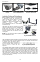
Mobile Awareness Fig 8: Sensor in Metal Bracket Fig 9: Sensor, Rubber Sleeve & Metal Bracket Fig 10: Waterproof Threaded Sensor Connectors Installation: Monitor and Wiring Harness Before installing the system, it is recommended to temporarily connect all components and perform a system function check. If the system does not operate properly, see the troubleshooting section of this manual. If further questions arise, please visit www.mobileawareness.com or contact Mobile Awareness directly.
VisionStat Plus Video Monitoring and Obstacle Detection Sensor System Installation: Monitor and Wiring Harness (Continued) Before applying power to the system; make any Camera and trigger wire connections. The 22-pin wiring harness’ wiring connections can be seen in the chart below. The RCA connectors can be used to connect a second Monitor to the system for secondary viewing.
Mobile Awareness Installation: Cameras Each Camera will have a 4-pin connection and be connected to the Monitor’s 22-pin wiring harness via an extension cable. The extension cables come in lengths of 5M, 10M and 20M. The length of the cable used should be determined by the length of the vehicle, including any passageway or route you take through the vehicle’s body to ensure a safe and secure connection.
VisionStat Plus Video Monitoring and Obstacle Detection Sensor System Installation: Cameras (Continued) Any additional Cameras will be connected directly to the Monitor’s wiring harness via extension cables. These Camera views will not provide Sensor readings. Only those connected with the ECU (which only supports one camera) will provide Sensor readings.
Mobile Awareness Installation: Side Cameras (Continued) Connect the included extension cable (s) prior to mounting the Camera to the Side Camera Frame. This will allow you to thread the metal connectors together, tighten them securely and then slide the rubber boot completely over the mated connectors. This will assure a watertight and trouble free connection.
VisionStat Plus Video Monitoring and Obstacle Detection Sensor System Sensor Installation 1) The width of vehicles vary. It is important to install the Sensors at the appropriate distance and location along the rear bumper or equivalent (see Figure 23). Assuming that the width of vehicle is L, then the space between Sensors is 1/4L (Sensors must be mounted S1, S2, S3, S4, from left to right).
Mobile Awareness Fig 26: Sensor “UP” Indicator Fig 27: Rear of Metal Bracket Assembly (oriented “UP”) Fig 28: Sensor Angle Metal Bracket (oriented “UP”) Sensor Installation (SE Version) The SE Mount is an enhanced mounting method that further protects the Sensors while providing alternative mounting options. The solid rubber compound SE Sensor Mount is designed to securely and conveniently attach the SenseStat Sensor Element to your vehicle.
VisionStat Plus Video Monitoring and Obstacle Detection Sensor System Sensor Installation (SE Version - continued) 2) Once the location and orientation are determined, mark and drill the 2 (two) Sensor mount holes (0.156” or 5/32”) to accommodate the #6-32 screws. Refer to Figure 32 for the proper hole spacing which is 2.20” or 56mm center to center.
Mobile Awareness Alternate Sensor Mounting Locations The system is designed to be installed with all 4 (four) Sensors aligned across the rear of the vehicle, preferably at a height ranging from 16” to 32” from the ground. When the Sensors are installed in a different layout (for example to detect a building overhang as shown on the right), please consider the following: Each Sensor detects objects in a circular area approximately 20” in diameter.
VisionStat Plus Video Monitoring and Obstacle Detection Sensor System Having all four Sensors in line, on the same plane, provides the best result. If you break the Sensor configuration up, for example two on top and two on bottom, you create a bigger gap between the Sensors, causing a large blind zone area. This blind zone area can lead to objects or people being undetected by the Sensors.
Mobile Awareness Menus The Monitors menu will consist of three screens: 1) Picture 2) Option 3) System 1) Picture: The Picture menu will give you the option of adjusting Brightness, Contrast, Color and Volume. Press the CH– button on the Monitor to scroll up and down to select your desired function. Press the ▲☼/▼☼ buttons on the Monitor in order to adjust the level of each setting.
VisionStat Plus Video Monitoring and Obstacle Detection Sensor System System Operation A) Automatic Self-Test: Whenever the system is enabled, it will perform a selftest. Any Sensors that are blocked or inoperable will display an error message denoted by E1, E2, E3 or E4 (Sensors numbered left to right facing the back of the vehicle). After the self-test, the system will automatically remove the icon display of any inoperable Sensor(s) and begin operating (even when a Sensor is malfunctioning).
Mobile Awareness Maintenance & Troubleshooting If the unit is not working properly, please review the following suggestions, prior to contacting Mobile Awareness: 1) Double check all connections, including all 4-pin Camera and extension cable connections, as well as the 22 pin wiring harness. 2) Check your power and ground connections. If utilizing a back-up Camera, be sure the Brown Trigger Wire (from the 22-pin wiring harness) is connected to the vehicle reversing light power source.
VisionStat Plus Video Monitoring and Obstacle Detection Sensor System Symptom Possible Causes and Solution No Picture Ensure that Cameras are connected properly. No Sound Ensure the volume is turned up to a desired level and not muted. Dark Picture Ensure brightness and contrast are adjusted correctly. Check whether the environment temperature is too low. No Color Adjust color settings.
Mobile Awareness Backing Safety Suggestions A commercial truck has extremely limited visibility. A large area behind the truck is invisible even with rear view mirrors properly adjusted. The larger the truck, the larger the blind spot areas. The driver must become familiar with the trucks blind spot area(s) so that precautions can be taken to avoid backing accidents. The best assurance to avoid an accident is by paying close attention to your surroundings.
VisionStat Plus Video Monitoring and Obstacle Detection Sensor System Notes 25
Mobile Awareness Notes 26
VisionStat Plus Video Monitoring and Obstacle Detection Sensor System 27
www.mobileawareness.com BCKS-2103-INS-R3.