
User Manual

2 D-303370 CLIP PG2 Installation Instructions
2.2 Regular Mounting
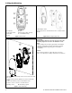
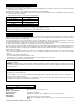
A. Enroll button
E. LEDs
B. Front tamper switch
F. Back tamper switch (optional)
C. RF Module
G. 3 Volt Lithium battery
D. Sensor
Figure 7. Internal View
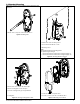
A. Back tamper switch
A back tamper alert is activated when the base is detached from
the wall.
Figure 8. Back Tamper (Rear) View
4
3
1
2
A
B
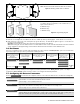
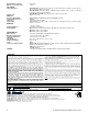
1. Drill two holes in the mounting surface and secure the base with
two screws.
2. For back tamper (optional) drill two holes and secure with two
screws.
3. Position the PCB in its proper location within the base.
4. Insert the screw to secure the cover with the base.
A. Mounting surface
B. Break-away segment
Figure 9. Surface Mounting
ATTENTION!
The back tamper switch becomes functional only when the
break-away segment is secured to the wall with a screw.
Notes:
1) After mounting, be sure that no gaps remain in the detector
housing. For example, in the area around the screw holes.
2) Remove the battery using your fingers, and not with a
screwdriver.
Caution!
Risk of explosion if battery is replaced by an incorrect type.
Dispose of used battery according to manufacturer's instructions.