
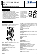
User's Manual


2
DE3633
3. INSTALLATION
3.1 Installation Hints
To minimize false alarms:
Do not aim at heat sources
Mount on solid, stable surfaces
Do not expose to air draughts
Do not install outdoors
Prevent direct sunlight from
reaching the detector
Keep wiring away from electrical
power cables
Do not install behind
partitions
3.2 Battery Insertion
It is recommended to power up the detector and let the target
receiver “learn” the transmitter’s ID before actual installation. This
can be done only after battery installation.
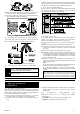
1st.Remove the front cover as shown in Figure 3.
Figure 3. Cover Removal
B. Insert the battery into the battery clip - observe polarity (see
Figure 4).
3rd. Press the tamper switch once and release it. This will perform
the reset necessary for smooth power up.
4th. Put the cover on and observe the LED. It will flash until the
detector stabilizes (within about 30 seconds).
3.3 Enrolling the Transmitter ID
Refer to the target receiver’s installation instructions and follow
the procedure given there for “teaching” the transmitter's ID. It is
much easier to carry out this operation in close proximity to the
receiver.
3.4 Mounting without Swivel Bracket
1st.Remove the front cover as shown in Figure 3.
2nd.Loosen the vertical adjustment screw, slide the PCB down
and remove it via the “keyhole” (see Figure 4).
Figure 4. Inside View
3rd.Punch out the mounting knockouts at the base (for surface
mounting) or mounting knockouts at the angled sides of the
base (for corner mounting).
Attention! The unit has a special tamper switch under the PCB. As
long as the PCB is seated firmly within the base, the switch lever will
be pressed against a special break-away base segment that is
loosely connected to the base (Figure 5). Be sure to fasten the
break-away segment to the wall. If the detector unit is forcibly
removed from the wall, this segment will break away from the base,
causing the tamper switch to open. It is advisable to pierce the
anti-tamper knockouts from within the base outward, while
pressing the rear surface of the break-away segment against a
piece of wood.
Figure 5. Anti-Tamper Break-Away Base Segment
4th.Hold the base against the wall at the selected location, mark
the drilling points, drill the holes and attach the base to the
wall.
5th.Return the PCB to its place: align the ”keyhole” with the head
of the vertical adjustment screw, press the PCB against the
base, slide the PCB up and temporarily tighten the screw.
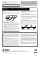
3.5 Mounting with Swivel Bracket
1st.Remove the front cover as shown in Figure 3.
2nd.Loosen the vertical adjustment screw, slide the PCB down
and remove it via the “keyhole” (see Figure 4).
3rd.Punch out the large knockout in the round bulge at the top
part of the base (see Figure 6).
4th.Assemble the bracket as shown in Figure 6.
Figure 6. Attaching the Bracket
5th.Rotate the bracket to the desired position (see Figure 7) but
do not yet tighten the screw fully.