
User's Manual
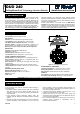
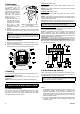
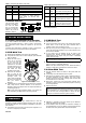


Table 1. Interpreting the States of the LEDs
GREEN RED Significance
Off Off No detection
On Off MW walk-test detection
Flashes Off PIR walk-test detection
Off On Alarm: MW + PIR detection
Flashes Flashes Trouble is being detected by the self
test circuitry, or Initial warm-up
routine (stops 60 seconds after
power up).
4.2 Mode Selector
The DIP switch mode
selector is mounted on
the unit’s PC board
(Fig. 3). It controls four
functions as demons-
trated in Fig. 5 and as
detailed in Table 2.
Figure 5. DIP Switch Mode Selector
Table 2. Mode Selector Switch Functions
Switch State Function Default
SW-1
OFF
ON
One motion event trips the PIR
Two motion events trip the PIR
ON
SW-2
OFF
ON
Alarm walk test is disabled*
Alarm walk test is enabled
ON
SW-3
OFF
ON
MW/PIR walk test is disabled*
MW/PIR walk test is enabled
ON
SW-4
OFF
ON
Output relay opens upon alarm
Output relay opens upon alarm
and when trouble is detected.
OFF
* Setting SW-2 and SW-3 to OFF does not disable the trouble
indication (flash/flash).
5. INITIAL ADJUSTMENT
5.1 Setting the Motion Event Counter
If you wish to set the PIR detector for maximum false alarm
immunity, shift DIP switch No. 1 (SW-1) to ON. In this position,
two consecutive motion events are required to trip the PIR
detector.
For faster catch performance, shift SW-1 to OFF. In this position,
only one motion event is required to trip the PIR detector.
5.2 PIR Walk Test
A. Rotate the MW RANGE control all the way toward MIN.
B. Verify that DIP switch SW-3 is set to ON (the green walk-test
LED is enabled).
C. Mount the front cover in
place: line up the ridge
on the cover with the
cavity in one of the two
projections on the base
circumference (Fig 6). Fit
the cover over the base,
and rotate the cover
clockwise until it stops.
D. Walk into the detector's
field of view at the
expected far edge of the
coverage area. The
green LED should flash
for up to 5 seconds each
time your motion is
detected.
F
igure 6. Remounting the Cover
E. If PIR detection is not obtained at the far edge of the coverage
area, verify that the infrared radiation is not blocked or
diverted by intervening objects such as large lampshades, air
conditioning ducts etc.
Note: If the green LED illuminates steadily, your motion has
been detected by the MW detector and not by the PIR.
5.3 MW Walk Test
A. Remove the front cover.
B. Verify that the MW range control is set to MIN and that DIP
switch SW-3 is set to ON (the green walk-test LED is
enabled). Close cover (see section 5.2 C).
C. Start by moving into the coverage area at the far edge. The
green LED should light steadily for up to 5 seconds each time
your motion is detected.
D. If your motion was not detected at the far edge of the
coverage area, advance the MW RANGE control slightly
toward MAX and try again until your motion is detected
reliably at the far edge.
Caution! The MW detection range must not exceed the far
edge of the desired coverage area.
E. Walk across the coverage area at various ranges and verify
that your motion is consistently detected.
Note: If PIR trips interfere with your test, disable the PIR by
inserting a small piece of cardboard in front of the sensor.
5.4 Alarm Walk Test
A. Set DIP switches SW-2 and SW-3 to ON (both LEDs are
enabled).
B. Temporarily mount the detector's cover in place.
C. Walk across the detector’s field of view in different directions,
at various distances from the detector, and verify proper
detection throughout the entire coverage area (the red LED
will illuminate for 2 to 3 seconds).
D. When done, remove the cover and set DIP switches SW-2
and SW-3 to OFF to prevent unauthorized people from tracing
the coverage pattern.
E. Remount the cover.
Attention! To assure proper function of the detector, the
range and coverage area should be checked at least twice a
year. Furthermore, it is recommended to perform a walk test
at the far end of the coverage pattern to assure an alarm
signal prior to each time the alarm system is armed.
6. WARNINGS
Although this detector is a highly reliable device, it does not
guarantee complete protection against intrusion. Even the most
sophisticated detectors can sometimes be defeated or may fail to
warn because:
A. The detector will not function if the DC power supplied to it is
incorrect or improperly connected.
B. Detection is confined to the area covered by the detection
pattern as adjusted by the installer.
C. A PIR detector does not provide full volumetric coverage of
the protected area. It can only detect motion that disturbs the
sensitive beam array spread within the protected space.
DE1826 3