
User Manual

D-303731 FLD-550 PG2 Installation Instructions 1
FLD-550 PG2
PowerG Wireless Flood Detector
Installation Instructions
1. INTRODUCTION
The FLD-550 PG2 is a fully supervised two-way indoor, PowerG flood detector, used to detect the presence of water based fluids at
any desired location. The FLD-550 PG2 sends the parameters of the specific alarm to the control panel using PowerG two-way
communications protocol.
The FLD-550 PG2 tamper switch is activated when the cover is removed.
A periodic supervision message is transmitted automatically. The control panel is thus informed, at regular intervals, of the unit’s active
participation in the system.
An LED lights whenever alarm or tamper events are reported. The LED does not light while a supervision message is being transmitted.
Operating power is obtained from an on-board 3 V Lithium battery. When the battery voltage is low, a “low battery” message is sent to the
receiver.
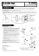
A. Clamp (1 of 3) – attach
slightly above flood
detector
B. Flood sensor
C. Water
D. Flood sensor cable
E. FLD-550 PG2
F. PowerG code alarm
G. Alarm system
Figure 1. Using the FLD-550 PG2
2. INSTALLATION
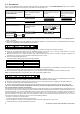
2.1 Mounting
1. Attach the flood sensor near the floor.
2. Secure the flood sensor and its cable to the wall using the three
wire clamps. One clamp should be fastened immediately above
the flood sensor. The flood sensor should be installed only in a
vertical position, and facing downward. The remaining two
clamps can be used as required (see Figures 1 and 2).
Note: To provide better protection against rats, it is
recommended that the flood sensor cable be placed inside a
metal/plastic pipe.
3. Attach the flood detector to the wall. The flood detector should
be placed as high up as possible on the wall to improve
communication and to prevent the flood detector itself from
coming into contact with water in the event of flooding.
4. Insert a flat-edged screwdriver into the slot and push upward to
remove cover.
5. Remove the screw and separate the cover from the base.
6. Remove the PCB board.
7. Mark and drill 2 holes in the mounting surface and fasten the
base with 2 countersunk screws.
Risk of explosion if battery is replaced by an incorrect type. Dispose
of used battery according to manufacturer's instructions.
Note: 868 MHz device is illustrated in the above example. The
same mounting procedure should be performed for 433 MHz and
915 MHz devices.
A. Transmission LED
B. 2 -3 m (recommended length)
C. Flood Sensor Cable
D. Water
E. Enroll button
F. Tamper switch
Note: Flood sensor height according to required flood detection.
Recommended 0-3 cm from floor.
Figure 2. Correct Mounting of the Flood Detector