
User Manual

2 D-303731 FLD-550 PG2 Installation Instructions
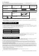
2.2. Enrollment
Refer to the PowerMaster panel's Installer's Guide and follow the procedure under the "02:ZONES/DEVICES" option of the Installer
Menu. A general description of the procedure is provided in the following flow chart.
Step 1 Step 2 Step 3 Step 4
Enter the Installer menu and select
“02:ZONES/DEVICES”
Select "ADD NEW DEVICE"
See Note 1
Enroll the device or enter the
device ID
Select the desired detector
number for the new flood
detector
Step 5 Step 6 Step 7
Configure Location parameter
Enter PARTITIONS.
See Note
2
Assign partitions to the detector
by pressing the
,
and buttons on
the panel
means scroll and select
Notes:
1. If the detector is already enrolled, you can configure the detector location parameter and assign partitions via the “Modify Devices”
option – see Step 2.
2. PARTITIONS will appear only if PARTITIONING was previously enabled in a panel that supports the Partitioning feature (for further
details, see "Partitioning" in the PowerMaster Installer Guide).
3. LOCAL DIAGNOSTICS TEST
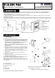
Before testing, separate the base from the cover (see Figure 2).
A. Verify that the FLD-550 transmits (the LED lights briefly) and that a tamper message was received by the panel.
B. When you are satisfied that tamper alerts are transmitted properly, put the cover on to return the tamper switch to its normal
(undisturbed) position and then secure the front cover to the base with the screw.
C. Bring the flood sensor into contact with water. Wait a few seconds and verify that the transmitter LED lights, indicating that
transmission is in progress. It is recommended to perform this test every month.
D. After 2 seconds the LED blinks 3 times.
The following table indicates received signal strength indication.
LED response Reception
Green LED blinks Strong
Orange LED blinks Good
Red LED blinks Poor
No blinks No communication
IMPORTANT! Reliable reception must be assured. Therefore, "poor" signal strength is not acceptable. If you receive a "poor" signal
from the device, re-locate it and re-test until a "good" or "strong" signal strength is received.
E. Dry the flood sensor using either blotting paper or a rag, thus restoring it to the undisturbed state, and then observe the LED.
Note: For detailed Diagnostics Test instructions refer to the control panel Installer's Guide.
4. MISCELLANEOUS COMMENTS
Visonic Ltd. wireless systems are very reliable and are tested to high standards. However, due to low transmitting power and limited
range (required by FCC and other regulatory authorities), there are some limitations to be considered:
A. Receivers may be blocked by radio signals occurring on or near their operating frequencies, regardless of the digital code used.
B. A receiver responds only to one transmitted signal at a time.
C. Wireless devices should be tested regularly to determine whether there are sources of interference and to protect against faults.
The user is cautioned that changes or modifications to the unit, not expressly approved by Visonic Ltd., could void the user’s
FCC or other authority to operate the equipment.
The digital circuitry of this device has been tested and found to comply with the limits for a Class B digital device, pursuant to Part 15 of
the FCC Rules. These limits are designed to provide reasonable protection against harmful interference in residential installations. This
equipment generates, uses and can radiate radio frequency energy and, if not installed and used in accordance with the instructions,
may cause harmful interference to radio and television reception. However, there is no guarantee that interference will not occur in a
particular installation. If this device does cause such interference, which can be verified by turning the device off and on, the user is
encouraged to eliminate the interference by one or more of the following measures:
– Re-orient or re-locate the receiving antenna.
– Increase the distance between the device and the receiver.
– Connect the device to an outlet on a circuit different from the one which supplies power to the receiver.
– Consult the dealer or an experienced radio/TV technician
MODIFY DEVICES
Z07.LOCATION Z07.PARTITIONS
Z07:P1 P2 P3
ID No. 240-XXXX
Z07:Flood Sens
ENTR ID:XXX-XXXX
ENROLL NOW or ADD NEW DEVICES
02:ZONES/DEVICES