
User's Manual

D-303015 KP-140 PG2, KP-141 PG2 Installation Instructions 1
KP-140 PG2/KP-141 PG2
Portable Remote Wireless 2-Way Keypad
User’s Guide
1. INTRODUCTION
KP-140 PG2 and KP-141 PG2 are 2-way PowerG wireless keypads for the
PowerMaster family control panels. The KP-141 PG2 is the same as the KP-140
PG2 but also includes a built-in proximity RFID tag reader. Both keypads enable
most common everyday user functions:
Arm and Disarm the alarm system.
Initiate Emergency, Fire and Panic alarms.
Control X-10 devices and PGM output (not to be enabled in UL Listed product).
Perform one of the AUX (auxiliary) predefined functions.
Review system Status.
When authorization is required, for example, to arm or disarm the system, the user
can enter his PIN Code via the built-in numerical keypad or alternatively present a
valid proximity tag to the built-in tag reader (only with KP-141PG2) located at "N" in
Figure 1.
In addition, the KP-140 PG2/KP-141 PG2 keypad supports panels featuring
Partitions. Partitioning allows you to have up to three controllable areas; each partition
can be armed and disarmed independently regardless of the status of the other two
partitions by the same or different users (see buttons marked "E" in Figure 1).
The keypads can be wall mounted using the supplied bracket or be used as
portable units. For compliance with various international standards, the keypads
are equipped with two tamper switches that can be configured to detect when the
cover of the battery compartment is removed or when the unit is removed from its
mounting bracket.
Note: For UL Listed Product, unit is not intended to be portable.
Other features of the KP-140 PG2/KP-141 PG2 keypad include:
Status, alarm memory, trouble and Ready / Not-Ready indications.
Automatic reporting of low battery voltage.
Keypad back lighting.
Exit/entry beeps
Tag reader can also be used to enroll proximity tags into the panel.
Long-life 4-5 years battery life expectancy (for typical use), 3 VDC lithium battery.
Note: For UL Listed product, the proximity feature may only be used to arm or
disarm the system.
Note: For UL Listed product, Models KP-140 PG2 and KP-141 PG2 are for
Supplemental Use only.
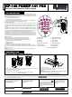
B
A
C
D
E
F
G
H
I
J
K
L
M
N
A. ARM HOME H. AUX / ENROLLMENT
B. ARM AWAY I. EMERGENCY
ALARM
C. DISARM J. FIRE
ALARM
D. X-10 / PGM K. PANIC
ALARM
E. PARTITION SELECTION L. BUZZER INDICATOR
F. ARM INSTANT M. LED INDICATOR
G. STATUS / ESCAPE N. TAG READER
Figure 1 - External View
2. INSTALLATION
2.1 Mounting and Battery Replacement
3
A
1
2
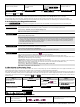
1. Drill 2 holes in mounting surface, insert wall anchors and fasten the bracket with 2 screws.
2. Place the "Visual Indications" sticker within the frame.
3. Slide the keypad into the bracket.
A. Magnet (activates back tamper when bracket is removed from the wall).
Figure 2 - Mounting
2
1
A
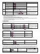
1. Slide out the cover.
2. Replace the battery (verify proper polarity) and close the cover.
A. Battery compartment tamper switch
Caution!
Risk of explosion if battery is replaced by an incorrect type. Dispose of
used battery according to manufacturer's instructions.
Figure 3 - Battery Replacement
2.2. ENROLLMENT
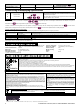
Refer to the PowerMaster panel's Installer Guide and follow the procedure under the "02:ZONES/DEVICES" option of the Installer Menu a general description of
which is provided in the following flow chart.
Step 1 Step 2 Step 3 Step 4
Enter the Installer menu and select
“02:ZONES/DEVICES”
Select "ADD NEW DEVICE"
See Note 1
Enroll the keypad by holding the
button and release it as soon as the
yellow LED lights. Alternatively, enter the
device ID (printed on the back of the
keypad)
Select the desired keypad
Number for the new keypad
See Note 2
MODIFY DEVICES
ID No. 370-XXXX
K06:Keypad
ENTR ID:XXX-XXXX
ENROLL NOW or ADD NEW DEVICES02:ZONES/DEVICES