KP-250 PG2 Advanced Two-Way Keypad User’s Guide Table of Contents 1. Introduction ................................................................................................................................................................. 3 2. Additional System Features ........................................................................................................................................ 3 Partitioning ..................................................................................
B.14 Programming the Scheduler ......................................................................................................................... 43 B.15 Enabling / Disabling Voice Option ................................................................................................................ 45 B.16 Adjusting the Volume of the Control Panel or External Box .......................................................................... 46 B.17 Serial Number..........................................
1. Introduction 1. Introduction KP-250 PG2 is a 2-way wireless PowerG keypad display device for use with the PowerMaster-10 G2 / PowerMaster-30 G2 / PowerMaster-33 G2 control panel (version 18 and higher). Up to 10 KP-250 PG2 keypads can be enrolled in the PowerMaster system. The PowerMaster-10 G2 / PowerMaster-30 G2 / PowerMaster-33 G2 is a highly advanced wireless alarm control panel produced by Visonic Ltd. 2.
2.
2. Additional System Features Once the progress indicator reaches 100%, RECORDING ENDED will be displayed. When you release the button, the display will revert to the normal status-displaying mode, but will also indicate that a message is waiting. For example: HH:MM READY MESSAGE Note: The message icon ( ) will also flash on the bottom of the display. Message Playback Message playback is performed by the control panel.
3. Arming and Disarming the System 3. Arming and Disarming the System Basic Arming and Disarming Following are a set of procedures for performing basic arming and disarming of the alarm system. Preparing to Arm Before arming, make sure that READY is displayed on the KP-250 PG2 keypad. HH:MM READY This indicates that all zones are secured and you may arm the system as desired.
3. Arming and Disarming the System PRESS RESULTING DISPLAY Move to interior zone (ARM HOME) AWAY/HOME ARM indicator on both the KP-250 PG2 keypad and PowerMaster panel lights steadily during the armed state. Disarming and Stopping Alarm Enter the protected premises via a delayed zone. Upon detecting your entrance, the system will start sounding the entry delay beeps alerting you to disarm the system before the entry delay ends.
3. Arming and Disarming the System Switching from ‘HOME’ to ‘AWAY’ You do not have to disarm the system - just press Vacate the premises before the exit delay expires. . The response will be the same as in ARMING AWAY above. Switching from ‘AWAY’ to ‘HOME’ You do not have to disarm the system - just press .
3. Arming and Disarming the System the last 10 seconds of the delay. You can silence this signal by pressing the arming button again.
3. Arming and Disarming the System Arming in the Latchkey Mode This mode, if enabled by the installer, is useful for a parent at work who wants to be sure that his children have returned from school and have disarmed the system. A special “latchkey” message will be sent out when the system is disarmed by a “latchkey user”. Latchkey users are holders of user codes or users of keyfob transmitters 5-8 (PowerMaster-10 G2) / 23-32 (PowerMaster-30 G2 / PowerMaster-33 G2).
3. Arming and Disarming the System Initiating Fire Alarm or Emergency Alarm You can generate a fire alarm or a silent emergency alarm in disarmed & armed states, as follows: PRESS RESULTING DISPLAY FIRE ALARM OR EMERGENCY for 2 seconds Then, if or when the system is in the disarmed state: HH:MM READY (alternating) READY MEMORY To stop the alarm, press and then key in your valid user code.
3. Arming and Disarming the System Adjusting the Volume of the Keypad Beeps The following diagrams show how to increase or decrease the loudness by clicking the <1> or<4> key on the KP-250 PG2 keypad (assuming that the volume was at minimum/maximum to begin with).
4. System Status and Indications 4. System Status and Indications Note: The icons and numbers shown on the above keypad drawing are for illustrative purposes only. When executing a command, the KP-250 PG2 keypad's LED blinks red once to indicate transmission of the command to the control panel. If the operation is successfully completed, the green LED lights momentarily and a "happy tune" sounds.
4. System Status and Indications General Indications The Ready/Not Ready, Alarm Memory, Trouble and Low Battery indications are provided via the indications in the following table: Indication What it Means What it Means KP-250 PG2 low battery.
4. System Status and Indications Alarm Indication Siren The PowerMaster system incorporates one or more high power sirens that sound in case of alarm. A siren can sound from either the control panel or from a device and may be a part of a system component. Alarm Type Graphic Representation of Signal Verbal Description of Signal Burglar / 24 hour/ Panic ––––––––––––––––––––––––––––––– ON continuously Fire ––– ––– ON - ON - ON - pause - ON - ON - ON - pause.....
5. Reviewing Troubles and Alarm Memory 5. Reviewing Troubles and Alarm Memory Alarm & Tamper Memory Indication The KP-250 PG2 retains in its memory alarm and “tamper” events that occurred during the last arming period. Note: Alarm events are memorized only after the “abort period”. This means that if you disarm the system immediately before the abort period expires - there will be no memory indication A.
5. Reviewing Troubles and Alarm Memory B. Displaying Trouble Information All trouble messages need to be reviewed and corrected as described below: EXAMPLE: The kitchen device - zone No. 9 - has reported a low battery – the living room device zone No. 15 - has been inactive, and an attempt to communicate a message to your telephone has failed. However, these troubles do not prevent the system from being “ready to arm”.
5. Reviewing Troubles and Alarm Memory Trouble Indications The trouble indications (illuminated TROUBLE indicator and flashing TRBL message) are cleared once you eliminate the cause of trouble. Fault What it means 1-WAY The device functions but cannot "hear" the panel. The control panel cannot configure or control the device. Battery consumption increases. There is no power supplied to the device. AC FAILURE The fire detector must be cleaned FIRE CLEAN COMM.
6. System Configuration 6. System Configuration This chapter explains the user programming features of your PowerMaster system using the KP-250 PG2 keypad. To access the User Settings menus, a KP-250 PG2 keypad must first be enrolled in the system. For instructions on how to enroll the KP-250 PG2 Keypad, refer to the KP-250 PG2 Installer’s Guide, section 11.4. The Master User has access to all the User Settings menus, while the User has access only to the bypass menus (see section B.
6. System Configuration 2 a. If you have not already changed your personal code number, use the default setting – 1111. b. Master User has access to all User Settings options. Other users have access only to the Bypass options. c. If you enter an invalid user code 5 times, the keypad will be automatically disabled for a pre-defined period of time and the message WRONG PASSWORD will be displayed. 3 The bypass options will be displayed in the User Settings menu only if enabled by the installer.
6. System Configuration AUTO-ARM TIME 12:00P Use to set the predetermined time for the Automatic Daily Arming if enabled (see AutoArm Enable setting). For further details and programming procedure see section B.11. PRIVATE REPORT Use to program the four private telephone numbers for reporting alarm and other event messages to private subscribers. For further details and programming procedure see section B.12. SQUAWK on Use to enable or disable the squawk sound i.e. arm / disarm feedback indication.
6. System Configuration 12:00 READY The system exits the [USER SETTINGS] menu and returns to the normal disarm state while showing the READY display. A.3 Buttons used for Navigation & Setting The keypad's buttons are used for various functions when programming. The following table provides a detailed description of the function or use of each button. Button Definition Navigation / Setting Function NEXT Use to move / scroll forward to the next menu options.
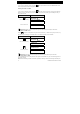
6. System Configuration A. To Bypass a Zone 1. SET ZONE BYPASS Enter the [USER SETTINGS] menu1, select the [SET ZONE BYPASS] 2 option and press Z01: READY Living Room . The first zone, Z01, is displayed. 3 4 Z01: P1 P2 P3 2. or Click the or button until the display reads the zone you wish to bypass (or clear bypass), for example, "Z04" for Zone 04. After several seconds the LEDs on the respective device starts flashing indicating "it's me". Z04: NOT READY Z04: P1 P2 P3 3. 4.
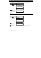
6. System Configuration B.2 Reviewing the Zone Bypass Scheme 1. Here you can quickly review the Bypass Scheme i.e. the zones that are set to be bypassed during the next arming session. REVIEW BYPASS Enter the [USER SETTINGS] menu and select the [REVIEW BYPASS]1 option and press 2. BYPASS LIST or .2 The display reads [BYPASS LIST] Click the or buttons repeatedly to review all bypassed zones in to exit. 9 ascending numerical order. When done, click 3. Z04: BYPASSED Z04: P1 P2 P3 Kitchen B.
6. System Configuration 5 a. If the zone you selected is "not bypassed", the display prompts you to press [ TO BYPASS]. However, if the zone you selected is already "bypassed", the display prompts you to press [ TO CLEAR]. b. To abort and return to the previous step press 6 7 or This menu is not displayed if Partition is enabled. The display now prompts you to press [ TO RECALL] i.e. to repeat the last used bypass scheme. To abort and return to the User Settings menu, press .
6. System Configuration User Codes 5-8 (PowerMaster-10 G2) / User Codes 23-32 (PowerMaster-30 G2 / PowerMaster-33 G2) are the same as user codes 2-4 (PowerMaster-10 G2) / 2-22 (PowerMaster-30 G2 / PowerMaster-33 G2) but can be assigned to "Latchkey" (child monitor) users. For a detailed explanation of the Latchkey application see Chapter 3. Partition Option (For information about Partition option - see APPENDIX B) Your alarm system can divide zones into up to 3 parts (groups) via the installer menu.
6. System Configuration B. To Set Partitions Authorization 6. User 06: 1234 1 2 3 The display will now enable you to set the partitions. 7 7. User 06: 1234 1 2 3 Press the button and use the keypad keys , , to change the status of the partitions 1, 2 & 3, respectively. 8 When you are satisfied with the setting, for example, User 6 is authorized with Partition 1 and 3 only, press ☺ Return to step 3 to confirm. ☺ sounds. The display confirms the Partition setting.
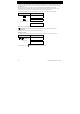
6. System Configuration 1. 2. DURESS CODE 2580 Enter the [USER SETTINGS] menu, select the [DURESS CODE] option and press DURESS CODE 2580 At the blinking cursor position, key in the Duress Code you wish to program, for example, 6973. 2, 3 DURESS CODE 6973 When the duress code you wish to program appears on the display, press .1 . 3. ☺ Return to step 1 A "Happy Tune" ☺ sounds and The display confirms the saved setting. 4 Additional Information (section B.
6. System Configuration 5. ☺ Go to step 5 or DEVICE ENROLLED T05:Tag (Prox) ☺ Return to step 2 the tag's details. 4 The display shows the allocated tag serial No (user No.), which is always the first free number, for example: [T01:Tag (Prox)]. To assign the tag to another user, for example, "User No. 5", key in [05] or alternatively click the or (Prox)] and then press button until the display reads [T05:Tag to confirm.
6. System Configuration 6. To delete the tag press the DELETE TAG button. A "Happy Tune" ☺ sounds and the display reads [DELETE TAG] and returns to step 3. 11 ☺ Go to step 3 Additional Information (section B.6) 1 For detailed instructions on how to select User Settings – refer to section A.1 and section A.2. 2 The display shows the first enrolled Tag (Tag No.1) of the 8 (PowerMaster-10 G2) / 32 (PowerMaster-30 G2 / PowerMaster-33 G2) tags.
6. System Configuration A. To Add (Enroll) a Keyfob 1. Enter the [USER SETTINGS] menu, select the [KEYFOBS] option and press KEYFOBS .1 2. ADD NEW KEYFOB 3. ENROLL NOW or ENTR ID:xxx-xxxx The display will read [ADD NEW KEYFOB]. 4 To enroll a new keyfob press . The display offers you two alternative methods to enroll a keyfob: A: ENROLL NOW: Press and hold the AUX button on the selected keyfob until 2 the LED is constantly on. This procedure completes the enrollment. 4a. DEVICE ENROLLED ID No.
6. System Configuration B. To Set Partitions Authorization 6. F05:PARTITIONS 7. F05:PARTITIONS 1 2 3 8. F05:PARTITIONS 1 2 3 ☺ Return to step 2 Press to enter partitions mode. Use the keypad keys respectively. 10 , , to change the status of the partitions 1, 2 & 3, When you are satisfied with the setting, for example, User 5 is authorized with Partition 2 and 3 only, press to confirm. 11 ☺ sounds. The display confirms the Partition setting. 12 A "Happy Tune" C.
6. System Configuration ☺ Go to step 3 DELETE KEYFOB ☺ sounds and the display reads [DELETE KEYFOB] and A "Happy Tune" returns to step 3. 14 Additional Information (section B.7) 1 For detailed instructions on how to select User Settings – refer to section A.1 and section A.2. 2 The LED will extinguish after several seconds. In case of difficulties in communication with the control panel, the LED may blink for several seconds more while trying to establish communication.
6. System Configuration A. To Set the Time Format 1. TIME & FORMAT Enter the [USER SETTINGS] menu and select the [TIME & FORMAT] option and press 2. EU FORMAT 24H TIME: 19:22 or US FORMAT-12H TIME: 03:15P .1 The display shows the currently selected time format. 2 Click the or button until the display shows the desired time format, for example, "US FORMAT-24H" and press to confirm . 3. B. To Set the Time 5 4.
6. System Configuration B.9 Setting the Date & Date Format Here you can program or adjust the built-in-calendar to show the correct date in the desired date format. You can select between a "mm/dd/yyyy" and a "dd/mm/yyyy" date format. Carefully read the section titled "Additional Information" according to the indicated references1 etc – see table at end of this section. A. To Set the Date Format 1.
6. System Configuration B.10 Enabling / Disabling Auto-Arming The PowerMaster system can be programmed to automatically arm itself on a daily basis at a predetermined time. This feature is useful especially in commercial applications, such as in stores, to ensure that the system is always armed and without having to assign security codes to employees. Here you can enable (activate) and disable (stop) the Auto-Arming. To set the Auto-Arming time – see section B.11.
6. System Configuration Additional Information (section B.10 - B.11) 1 2 For detailed instructions on how to select User Settings – refer to section A.1 and section A.2. The display shows the current setting, for example, [AUTO-ARM enable]. You can now select either to enable or disable auto-arming using the or button. symbol now appears next to the newly selected option.
6. System Configuration REPORTED EVENTS disable report 4. or REPORTED EVENTS alarms The display shows the currently selected option. Click the or button until the display reads the event group you wish to be reported via private phones, for example, [alarms]. 3 5. When you are satisfied with the setting, press REPORTED EVENTS alarms to confirm. A "Happy Tune" ☺ sounds. The display confirms the set events to be reported. 5, 12 ☺ B. To Program a Private Phone 6.
6. System Configuration 13. When you are satisfied with the setting, press REDIAL ATTEMPTS 4 alarms to confirm. ☺ sounds. The display confirms the set number of redial A "Happy Tune" attempts. 5, 12 D. To Program two-way voice communication 14. REDIAL ATTEMPTS 4 attempts Click the press or button until the display reads [Two Way Voice] and . or Two way voice enable 15. Two way voice enable 16. or Two way voice disable The display shows the currently selected option.
6. System Configuration TEL.ACKNOWLEDGE by all ack A "Happy Tune" method. 5, 12 ☺ sounds and the display confirms the set acknowledge SMS REPORT A. To Program Events to be Reported by SMS 1. SMS REPORT Enter the [USER SETTINGS] menu, select the [SMS REPORT] option and press .1 2. REPORTED EVENTS disabled REPORTED EVENTS disabled 3. or When the display reads [REPORTED EVENTS] press . The display shows the currently selected option.
6. System Configuration Additional Information (section B.12) 1 For detailed instructions on how to select User Settings – refer to section A.1 and section A.2. 2 This option allows you to program the events to be reported. To program telephone numbers, click the or button until the display reads the desired option. 3 The display shows the currently selected option (indicated by a the or symbol), for example, "disable report".
6. System Configuration "disable" - disables 2-way voice communication with private telephones. 11 You can select between: "by single ack" – an acknowledge signal from only a single telephone will stop the reporting process. "by all ack" – an acknowledge signal from all telephones is required to stop the reporting process. 12 You can now, select other options, end this session – (see section A.1 and section A.2), or quit programming (see section A.3). B.
6. System Configuration B.14 Programming the Scheduler The PowerMaster system includes a PGM output that can be used to open and close an electrically-controlled gate, or to control a preferred electrical device via keyfobs or according to a programmable weekly time schedule. Here you can schedule the PGM output for up to 4 different ON/OFF time activations per any desired day or days of the week. In addition, you can schedule a "Daily" schedule that applies to every day of the week.
6. System Configuration 8. Start time HH:MM 10:30 The display shows the current setting of the start time. 5 Start time HH:MM 00:30 Use the numerical keypad to set or change the operation ON (start) time, for 6 example, “00:30”. 9. When you are satisfied with the setting, press ☺ Go to step 10 to confirm. ☺ sounds and the display confirms the saved start time. A "Happy Tune" To set the stop time, continue to step 10. E. To Set the OFF (Stop) Time 10.
6.
6. System Configuration or Click the or button until the display reads the desired setting, for example, "disable" and press to confirm. 3 VOICE OPTION disable A "Happy Tune" ☺ sounds and the display confirms the saved setting. 3. 4, 5 Additional Information (section B.15) 1 For detailed instructions on how to select the Setting Options – refer to section A.1 and section A.2. 2 a. The display shows the currently selected setting (indicated by a symbol), for example, "enable". b.
6. System Configuration Additional Information (section B.16) 1 For detailed instructions on how to select the Setting Options – refer to section A.1 and section A.2. 2 The display shows the currently selected setting (indicated by a symbol). 3 4 indicates the lowest volume level and indicates the highest. You can now select another option in the User Settings menu (see section A.1 and section A.2), or quit programming (see section A.3). B.
7. Advanced Features 9. KP250 cat.number 70245100 Displays the KP-250 PG2 keypad catalog number. 10. RSU VERSION 7S702415 K01.034 Displays the software upgrade communicator version 11. BOOT VERSION 7S702412 K01.022 Displays the software upgrade boot/programmer version Return to step 2 3 4 , Additional Information (section B.17) 1 For detailed instructions on how to select the Setting Options – refer to section A.1 and section A.2. 2 Refers to PowerMaster-30 G2 only.
7. Advanced Features Automatic ON/OFF Control You can select two of four options: By Timer ON By timer OFF By sensor ON By sensor OFF The presently active options are shown with a dark box ( button. ) at the far right. To view the 2 other options click the A presently inactive option is shown without a dark box at the far right. The dark box will appear if you click the option is displayed. A “Happy Tune” indicates successful saving of a new option.
8. Periodic Test by User Code PRESS RESULTING DISPLAY 8. Periodic Test by User Code The components of your security system are designed to be maintenance-free as much as possible. Nevertheless, it is mandatory to test the system at least once a week and after an alarm event to verify that all system sirens, detectors, keyfobs, keypads and other peripherals function properly. Proceed as described in this section and if there is any problem, notify your installer at once.
8. Periodic Test by User Code is currently being tested. First the panel siren sounds for 3 seconds after which the PowerMaster system will automatically repeat the procedure for the next siren enrolled in the system until all sirens are tested. 5 You should listen to the sirens sounds and make sure that all sirens sound. Once all the sirens have been tested, the control panel will now test the sirens of smoke sensors that are enrolled in the alarm system.
8. Periodic Test by User Code Z01 CONTACT alternates between the device number, the device type (e.g. magnetic contact, keyfob, keypad, etc.), and the device location. The test is performed by activating each device as explained in point 8 in the table below. Z01 NOT ACTIVE FRONT DOOR Z01 IS ACTIVATE Z01 CONTACT Once the device has been activated, the display will change accordingly. 12. 13. Click DEVICE TESTS END to scroll through the list of all untested devices.
8. Periodic Test by User Code Periodic Test per Partition In addition to the regular Periodic Test, you can also test zones for enrolled sensors (excluding temperature sensors and sirens) that are assigned to a selected partition. To conduct the periodic Test per Partition HH:MM READY 1. 2. TROUBLE SELECT PARTITION 1 Make sure the selected partition is disarmed and the other partitions are not in exit or entry delay and then press the partition ( ) button.
8. Periodic Test by User Code 9. Press .5 ☺ Return to step 3 Additional Information (Periodic Test per Partition) 1 Partitioning must be enabled by your installer. 2 If you have not already changed your personal code number, use the default setting – 1111. 3 4 5 54 To abort, press the button; the display reads [ TO Exit]. Press the button.
9. Maintenance 9. Maintenance Replacing Wireless Devices Batteries The wireless devices supplied with your system are powered by batteries that last several years, in normal use. However, if and when a battery becomes weak, the device itself sends a “low battery” message to the control panel, and a low battery trouble message is displayed together with the zone information (see Chapter 5 – Trouble Indications).
9. Maintenance 3. Click the CPU LOW BATTERY 12/04/11 15:14 F03 DISARM 15/03/11 08:37 4. button. The latest event will be shown. The event is displayed on two rows, for example, "CPU LOW BATTERY" then "12/04/11 15:14". The display will be shown until clicking until the event log times out (4 minutes). Click the again to move to the next event or button as many times as necessary to read all the required data.
APPENDIX A: Specifications APPENDIX A: Specifications Frequency Band (MHz) Communication Protocol Battery type Battery Life Expectancy Low Battery Threshold Power source Back light Operating Temperature Humidity Dimensions (WxLxD) Weight (including battery and bracket) Mounting Color Europe and rest of world: 433-434, 868-869 USA: 912-919 PowerG Four 1.5V AA Alkaline batteries 3 years (for typical use). 3.8 V Battery: 4.
APPENDIX B: Partitioning Arming/Disarming a Single Partition To arm/disarm a single partition, press the or 3. Then, press the / or button on the KP-250 PG2 and then press the Partition number: 1; 2; button. B3. The Show Function The show function is enabled during single/all partition(s) status and displays information that is relevant to the selected or all partitions. Show All Partitions In Ready mode press memory / status content.
APPENDIX B: Partitioning Table A1 summarizes the behavior of the different zone types in a common area. Table A1 – Common Area Definitions Common area zone types Definition Acts as defined only after the last assigned partition is armed AWAY or HOME. In case that one of the partitions is disarmed, an alarm initiated from this zone is ignored for all assigned partitions. Delay zones Delay zones will not trigger an entry delay unless all assigned partitions are armed.
APPENDIX C: Glossary APPENDIX C: Glossary This list of terms is arranged in alphabetical order. Abort Period: When an alarm is initiated, the internal built-in sounder is activated first for a limited period of time which is the abort period set by the installer. If you cause an alarm accidentally, you can disarm the system within the abort period before the real sirens start and before the alarm is reported to the remote responders.
APPENDIX C: Glossary Forced Arming: When any one of the system zones is disturbed (open), the alarm system cannot be armed. One way to solve this problem is to find and eliminate the cause for zone disturbance (closing doors and windows). Another way to deal with this is to impose forced arming - automatic de-activation of zones that are still disturbed upon termination of the exit delay. Bypassed zones will not be protected throughout the arming period.
APPENDIX C: Glossary level of the alarm system. Zone: A zone is an area within the protected site under supervision of a specific detector. During programming, the installer allows the control panel to learn the detector’s identity code and links it to the desired zone. Since the zone is distinguished by number and name, the control panel can report the zone status to the user and register in its memory all the events reported by the zone detector.
APPENDIX D: Compliance with Standards APPENDIX D: Compliance with Standards Designed to comply with Standards Europe: EN 300220-1, EN 300220-2, EN300330, EN301489, EN60950, EN50131-1, EN50131-3, EN50131-6. The KP-250 PG2 is compatible with the RTTE requirements - Directive 1999/5/EC of the European Parliament and of the Council of 9 March 1999 and EN50131-1 Grade 2 Class II.
WARRANTY Visonic Limited (the “Manufacturer") warrants this product only (the "Product") to the original purchaser only (the “Purchaser”) against defective workmanship and materials under normal use of the Product for a period of twelve (12) months from the date of shipment by the Manufacturer.