MC-302E PG+ Wired Input Door/Window Magnetic Contact Installation Guide Installation guidelines The reference to MC-302E PG+ throughout this manual includes the model MC-302E P9M0. CAUTION: Only qualified personnel may install this equipment. Place this device in nonhazardous indoor locations only. Important: Check the device and the entire alarm system weekly to ensure optimal performance.
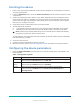
Enrolling the device 1. 2. 3. 4. 5. Refer to the control panel installation manual for the complete set of enrollment instructions and testing procedures. From the Installation menu, enter the Device enrollment menu and select the option to add a new device. Remove the battery pull-tab to power on the device and begin the auto-enrollment process. If the battery pull-tab is not available or if the device does not automatically enroll, open the device cover to trigger the enrollment.
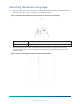
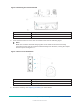
Mounting the device using tape 1. Peel the release liners off the two strips of double-sided adhesive tape and attach the tape to the back of the device and the magnet. See the following figure. Figure 2: Double-sided adhesive tape placement on the device and magnet 2. Callout Description A Double-sided adhesive tape Place the device on the frame of a window or door and place the magnet on the moving surface of the window or door itself, directed according to the positioning marks.
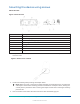
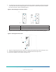
Mounting the device using screws About this task: Figure 4: Internal view Callout Description A Flexible electronic board retainer B Break-away segment C Electronic board edge supports D Mounting holes E Wiring inlet F Terminal block G Enroll button H Tamper switch 1. To open the device cover, use a screwdriver to loosen the cover screw and separate the base from the cover. Figure 5: Device cover removal 2. Remove the battery while pressing the tamper switch.
Figure 6: Removing the electronic board 4. Callout Description A Electronic board B Retainer Screw the device base on to the door or window frame. See the following figure. Note: Make sure to fasten the break-away segment to the frame. If the device is forcibly removed from the wall, this segment will break away from the base, causing the tamper switch to open. See Figure 7 A. Figure 7: Device screw installation 5.
. To reattach the electronic board to the base, flex the retainer and place the electronic board under the electronic board edge supports. Then release the retainer back in place to fasten the electronic board. See the following figure. Figure 8: Reattaching the electronic board 7. Callout Description A Electronic board edge supports B Retainer Clip the cover onto the device base and tighten the cover screw. See the following figure. Figure 9: Closing the device cover 8.
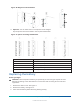
Figure 10: Magnet screw installation 11. Optional: You can add 3 mm or 7 mm spacers to the magnet. Clip the spacers onto the bracket in the required combination. Figure 11: Spacer mounting combinations Callout Description A Bracket + 3 mm spacer B Bracket + 7 mm spacer C1 Bracket only C2 3 mm spacer only C3 7 mm spacer only Replacing the battery Before you begin: CAUTION: Risk of explosion if battery is replaced by an incorrect type.
Figure 12: Battery removal and insertion 4. 5. Press down on the battery until it fits into place. Close the device cover and fasten the cover screw. See Figure 9. Note: After restoring a low battery, the system may take up to 5 minutes to clear the trouble. Wiring the auxiliary input About this task: The auxiliary input is programmable as either Normally Open (NO), Normally Closed (NC), End Of Line (EOL), Double End of Line (DEOL), and Triple End of Line (TEOL). 1. Remove the device cover. See Figure 5.
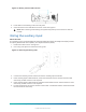
Figure 14: Alarm circuit options with EOL resistors 7. Callout Description A NO switch B NC switch C EOL: NO switch; 5.6 kΩ resistor D EOL: NC switch; 5.6 kΩ resistor E DEOL: NC switch only; R1=5.6 kΩ resistor; S1=tamper R2=5.6 kΩ resistor; S2=Alarm F TEOL: NC switch only; R1=5.6 kΩ resistor; S1=tamper R2=5.6 kΩ resistor; S2=alarm R3=10 kΩ resistor; S3=fault S2 and S3=masking Close the device cover and fasten the cover screw. See Figure 9.
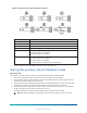
Figure 15: EOL Wiring Example Directional magnet distances for event triggers The following figure and table display the directional magnet distances that trigger open or close events. Figure 16: Range coverage directions Table 2: Directional magnet distances for event triggers Non-metallic surface Opening Supports Closing Metallic surface Direction Opening Closing 24 mm (0.94 in.) 20 mm (0.79 in.) X 9 mm (0.35 in.) 7 mm (0.27 in.) 15 mm (0.59 in.) 12 mm (0.47 in.) Y 12 mm (0.47 in.
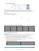
Table 3: Signal strength indication LED response Reception Red LED blinks Poor No blinks No communication Important: Reliable reception must be assured. Therefore, poor signal strength is not acceptable. If you receive a poor signal from the device, relocate it and re-test until a good or strong signal strength is received. Note: It is recommended to have a strong signal strength and you must verify the signal strength using the control panel's diagnostic test.
Compliance with standards MC-302E PG+ complies with the following standards: MC-302E P9M0 FCC (915 MHz): 47CFR part 15.247 FCC Compliance Statement This device complies with FCC Rules Part 15 license-exempt standard(s). Operation is subject to two conditions: (1) This device may not cause harmful interference, and (2) this device must accept any interference that may be received or that may cause undesired operation.
W.E.E.E Product recycling declaration For information regarding the recycling of this product you must contact the company from which you originally purchased it. If you are discarding this product and not returning it for repair then you must ensure that it is returned as identified by your supplier. This product is not to be thrown away with everyday waste. Directive 2012/19/EU Waste Electrical and Electronic Equipment.
warning or protection. The Products, properly installed and maintained, only reduce the risk of such events without warning and it is not a guarantee or insurance that such events will not occur. Conditions to Void Warranty: This warranty applies only to defects in parts and workmanship relating to normal use of the Products.
the Seller freight pre-paid and insured. All freight and insurance costs are the responsibility of the Buyer and are not included in this Warranty. This warranty shall not be modified, varied or extended, and the Seller does not authorize any person to act on its behalf in the modification, variation or extension of this warranty. This warranty shall apply to the Products only.
©2022 Johnson Controls. All rights reserved. JOHNSON CONTROLS, TYCO and VISONIC are trademarks and/or registered trademarks. Unauthorized use is strictly prohibited. D-308441 MC-302E PG+ Rev.