
User's Manual


DE2460U 1
MCM
MCMMCM
MCM-
--
-140
140140
140
Wireless Remote Commander
User’s Guide
1. INSTRODUCTION
1. INSTRODUCTION1. INSTRODUCTION
1. INSTRODUCTION
The MCM-140 is a wireless remote control unit for the PowerMax
system. It enables the user to arm/disarm the alarm system, to
initiate emergency/fire/panic alarms, to perform one of the AUX
(auxiliary) functions (see Note 3 in Section 6) and to turn lighting
devices on and off. The keypad includes an RF transmitter that
sends out a differently coded RF signal for each command.
The main features of the MCM-140 are:
• Automatic reporting of low battery voltage.
• Visual indications by red/green/amber LED.
• Keypad back lighting (selectable)
• Various audible signals sounded by the buzzer in response to
specific actions.
• Automatic supervision messages at 60 minute intervals.
• Long-life 3 VDC lithium battery.
• Wall mounting option.
• Friendly programming.
The red LED lights during transmission. The amber LED lights
during the programming process (and during transmission if
battery voltage is low). The green LED lights upon each
keystroke.
LED Indications
Description Symbol
Blinks at a fast rate - - - - - - -
Blinks at a slow rate _ _ _ _ _
Lights steadily (during transmission) ________
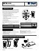
Figure 1 - External View
Keypad Buzzer Sound
Description Symbol
Short single beep, upon pressing a key
2 short beeps, in the programming process
(par. 4.3 & 4.5)
Success (victory) melody
Failure beep
2. SPECIFICATIONS
2. SPECIFICATIONS2. SPECIFICATIONS
2. SPECIFICATIONS
Transmitted ID Type: PowerCode and CodeSecure
PowerCode - Used for Lights 1-7, Light 8 (PGM controlled),
Fire and Emergency functions
CodeSecure - Used for Home arming, Away arming, Disarming,
Aux and Panic functions
Operating Frequency (MHz): 315, 433.9 and 868.95
Battery: 3 VDC, Lithium battery, CR123A
Back light illumination: Selectable on/off
Dimensions (HxWxD): 127 x 70 x 24 mm (5 x 2-3/4 x 31/32 in.)
Operating Temperatures: 0
°
-49
°
C (32
°
-120
°
F)
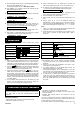
3. MOUNTING AND BATTERY REPLACEMENT
3. MOUNTING AND BATTERY REPLACEMENT3. MOUNTING AND BATTERY REPLACEMENT
3. MOUNTING AND BATTERY REPLACEMENT
Figure 2 - Mounting
Figure 3 - Battery Replacement