
User's Manual

D-301850 1
MCT-220
Wireless Emergency Button
User Guide
1. INTRODUCTION
1.1 General
The MCT-220 enables people, for example senior citizens in their
home environment, to transmit an emergency call when they are
at some distance from their communication unit.
1.2 Additional Features
• Can be used for panic alarm, when used with a Visonic Amber
or PowerMax family system.
• Can be used for X-10 devices activating when used with a
Visonic PowerMax family system.
• An auxiliary sensor can be connected to the MCT-220. When
the sensor is in an alarm state, the MCT-220 sends an alarm
message from its auxiliary channel.
• Enables people to answer incoming calls when the telephone is
out of reach, when used with a Visonic Amber family system.
• MCT-220 button pressing period - 2 seconds or 300
milliseconds (selectable by an internal function selector).
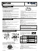
Figure 1 – MCT-220
• Supervision signal is regularly transmitted to the
communication unit.
• In low battery voltage state, an alarm message is sent to the
communication unit and the MCT-220 button blinks during
transmission.
• Push button back light can be switched On/Off by an internal
function selector.
• Auxiliary input E.O.L / Normally Close type can be selected by
an internal function selector.
• Auxiliary input alarm restore message can be enabled /
disabled (selected by an internal function selector).
• Water resistant.
2. SPECIFICATIONS
GENERAL
Compatibility: Compatible with all Visonic control panels and
receivers.
Operating Frequencies (MHz): 315, 433.92, 868.95 or 869.
ELECTRICAL
Internal Battery: 3V battery type CR123
Note: Dispose of used battery according to manufacturer's
instructions.
Current Consumption: 20µA
Battery Life Expectancy: 5 years (for one alarm per day)
ENVIRONMENTAL
Operating Temperature: 0° to 50°C (32° to 122°F)
Standards: Designed to comply with FCC CFR 47 Part 15, UL 1637,
Directive 1999/5/EC, EN 50131-2, Grade 2, Class II, RSS-210.
PHYSICAL
Dimensions (Diameter x H): 90 x 35 mm (3-1/2 x 1-3/8 in)
Weight: 110g (3.9 oz.)
Color: White
Note: The manufacturer is not responsible for any radio or TV
interference caused by unauthorized modifications to this
equipment. Such modifications could void the user's authority to
operate the equipment.
This device complies with Part 15 of the FCC Rules and RSS-210 of
Industry and Science Canada. Operation is subject to the following
two conditions: (1) This device may not cause harmful interference,
and (2) this device must accept any interference received, including
interference that may cause undesired operation.
This
device complies with the essential requirements and provisions
of Directive 1999/5/EC of the European Parliament and of the Council
of 9 March 1999 on radio and telecommunications terminal equipment.
3. PREPARATION FOR USE
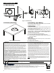
3.1 Cover Removal
1 2
COVER
BASE
Figure 2 – Cover Removal
3.2 Function Selector Setting
The MCT-220 has a 4 lever switch (see Fig. 3). Each switch lever
allows you to select one of two options.
BATTERY
MOUNTING HOLE
FUNCTION SELECTOR
WIRING KNOCKOUT
MOUNTING HOLE
AUXILIARY INPUT TERMINALS
Figure 3 – Internal View
Set the switches as desired (see table 1)
prior to applying power. Use a ball point pen
or another pointed object to shift the switch
levers. The ON position is indicated on
the switch body.
ON
1234
Figure 4
Function Selector
Table 1. Function Selector Description
Function Pos. Selected Option Default
ON Button's back light ON SW1
Back light ON/OFF
OFF Button's back light OFF
ON
ON Aux. input is E.O.L. (47 kΩ)SW2 Aux. input type
selector (*)
OFF Aux. input is N.C.
OFF
ON Aux input Restore events
are reported
SW3
Auxiliary input
restore reports
enable/disable (**)
OFF Aux. input restore events
are not reported
ON
ON 2 seconds SW4 Pressing period of
push button
OFF 300 milliseconds
OFF
(*) SWITCH SW2 determines whether the auxiliary input will behave
as a 47kΩ end-of-line (E.O.L.) input or as a normally closed
(N.C.) input.
(**) SWITCH SW3 determines whether the MCT-220 will report a
restore event when the auxiliary input restores from an alarm
condition.
3.3 Battery Insertion
Insert battery (see Figure 3) – Verify proper polarity.
Note: Dispose of used battery according to its manufacturer's
instructions.