
User's Manual

D-305291 MCT-340 SMA Installation Instructions 1
MCT-340 SMA
Wireless Contact Sensor
Installation Instructions
1. INTRODUCTION
The MCT-340 is a fully supervised, wireless magnetic contact sensor, for
use with iControl H.A. 1.2 control panels. The sensor includes a built-in
reed switch (that opens upon removal of a magnet placed near it).
The MCT-340 tamper switch is activated when the cover is removed.
A periodic supervision message is transmitted automatically. The target
receiver is thus informed, at regular intervals, of the unit’s active
participation in the system.
Operating power is obtained from an on-board 3 V Lithium battery. When
the battery voltage is low, a “low battery” message will be sent to the
receiver 30 days before expiration of battery life.
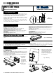
Pairing
LED
Magnet
Fig. 1 –
External View
2. SPECIFICATIONS
WIRELESS
Frequency: 2.4 GHz as per IEEE 802.15.4
Tamper Alert: Reported when a tamper event occurs and in any
subsequent message, until the tamper switch is restored.
Supervision Message: Signaling at 27-minute intervals.
Transmission Range in Open Area: Up to 280 meters (iControl panel)
ELECTRICAL
Internal Battery: 3V Lithium battery, type CR2032. Use Varta only.
Nominal Battery Capacity: 230 mAh
Battery Life Expectancy: 3 years (for typical use).
Note: Inability to connect with wireless network, or wireless link quality no
higher than 20% may significantly reduce the expected battery life.
Battery Power Test: Performed immediately upon battery insertion and
periodically every several hours.
Battery Supervision: Automatic transmission of battery condition data as
part of any status report.
ENVIRONMENTAL
Operating Temperature: 0°C to 55°C (32°F to 131°F).
Dimensions: 66 x 25 x 10 mm (2-9/16 x 1 x 6/16 in.)
Weight (including battery): 15g (0.5 oz)
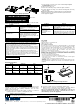
3. ACTIVATING THE SENSOR
To activate, pull the strip (from either side) that protrudes from the back of the
sensor.
Activation
strip
Fig. 2 – Activation Strip
4. PAIRING/DEFAULTING THE SENSOR
To pair the sensor to the control panel, you must set it to pairing mode.
First set the panel to pairing mode and then the sensor.
1. Press and hold down the sensor’s tamper switch (see Figure 4-4).
2. Insert the battery into the sensor (see Figure 4-4).
3. Release the tamper switch within 4 seconds (the LED blinks 3 times
every 5 seconds).
4. Complete the pairing procedure on the control panel (see the pairing
instructions in the control panel’s installation guide).
5. INSTALLATION
CAUTION: This equipment shall be installed by Service Personnel in
non-hazardous indoor locations only.
5.1 Mounting
NOTE: It is highly recommended to attach the transmitter to the top of the
door/window on the fixed frame and the magnet to the movable part (door or
window). Make sure that the magnet is located not more than 6 mm (0.25
in.) from the transmitter’s marked side.
The transmitter should be mounted on the fixed surface and the magnet
on the moving surface (see Figure 3).
A
1
1. Peel away the
release liners
from the two
strips of double-
sided adhesive
tape and attach
to the device and
magnet.
A. Double-sided
adhesive tape
2
2. Align the device with the magnet
according to the location marks
and fasten the device and magnet
to the mounting surface. The
transmitter should be mounted on
the fixed surface and magnet on
the moving surface.
Fig. 3 – Mounting
5.2 Battery Replacement
1
2