
User's Manual


DE3643 1
MCT-430
Supervised Wireless PowerCode Smoke Detector
Installation Instructions
1. INSTALLATION SUMMARY
1.1 General Description
The MCT-430 is a low profile, battery operated, photoelectric
smoke detector which shares its housing with a UHF PowerCode
type transmitter. It has a 57°C (135°F) fixed temperature heat
detector and a built-in sounder. The detector sends out the
following messages to the control panel:
• Smoke alarm
• Heat alarm
• Tamper alert
• Low battery alert
• Trouble message (when heat sensor malfunctions)
• Service alert (degraded smoke detection sensitivity - internal
screen requires cleaning).
During normal and low battery conditions, the LED flashes
approximately once every 40 seconds. The smoke/heat detector
will sound its built-in temporal horn when smoke activates the
detector (the LED flashes rapidly), or when the air temperature
reaches 57°C (135°F). A message is also sent to the wireless
control panel. After the horn stops, a RESTORE message is
transmitted to the control panel and the ID number can be
cleared from the panel. The built-in Drift Compensation algorithm
automatically maintains the sensitivity of the detector. Once the
detector reaches its limit of compensation, it transmits a
maintenance signal to the panel. When maintenance is required,
the LED stops flashing.
The maintenance signal fully complies with the sensitivity test
requirement specified in NFPA 72, 7 - 2.2.
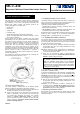
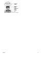
Figure 1. General View
1.2 Power Up and Initial Test
The smoke detector is supplied with two 3V batteries seated
within their holder but insulated from the battery terminals.
A. Turn the detector upside down and pull out the paper tab that
insulates the batteries from one of the terminals.
B. Insert a sharp object into the test switch hole and push the
switch in continuously, until the built-in horn sounds (about
2.5 seconds after depressing the button). The sounding
sequence is: 3 beeps - short break - 3 beeps ......and so on
until you release the switch. In addition, the LED will flash
rapidly a few times. This means that the smoke detection
section is working properly.
1.3 Enrolling Transmitter’s Power- Code ID
The detector includes a tamper switch that causes a tamper alert
when the main body is separated from its mounting bracket. This
switch protects the unit against unauthorized handling.
The detector has two separate PowerCode IDs:
• The first ID is linked to messages containing alarm, low
battery and supervision data.
• The second ID is linked to messages containing tamper and
maintenance data such as “clean” and circuit trouble.
Enrolling process to the PowerMax is differennt from the enrolling
process to other versions of the PowerMax (PowerMax+,
PowerMax GSM....), as described in par. 1.3.1 and 1.3.2.
1.3.1 Enrolling to PowerMax Control Panel
It is necessary that the control panel will learn the two IDs before
the detector is actually mounted in place. This is best carried out
in close proximity to the control panel. Each ID must be enrolled
to a separate zone of the control panel.
A. Refer to the control panel’s installation instructions and follow
the procedure given there for enrolling transmitter IDs in the
control panel's memory.
2nd. When required to initiate a transmission for enrollment of
the first ID, activate the test switch (see fig. 1) until the built-
in horn sounds (see Para. 1.2B).
C. When you are instructed to initiate a transmission for
enrollment of the second ID, separate the detector from the
bracket to activate a tamper message.
Important: If the second ID is not learnt by the control panel,
the maintenance and tamper messages will not be received.
Note: The PowerMax control panel can not distinguish
between “clean” and circuit trouble data. Upon receiving a
maintenance alert, clean the internal screen as described in
Para. 5.2. If the maintenance alert persists, the trouble is
probably due to a circuit failure.
1.3.2 Enrolling to Other Versions of PowerMax
(PowerMax+, PowerMax GSM...)
To enroll the transmitters IDs to the PowerMax+, PowerMax GSM
and above, it is necessary to enrol only one ID, the first ID or the
second ID (for IDs description refer to par. 1.3). When either ID
is enrolled to one zone, the second ID is automatically enrolled.
The enrolling process is as follows:
A. Refer to the control panel’s installation instructions and follow
the procedure given there for enrolling transmitter IDs in the
control panel's memory.
2nd. When you are instructed to initiate a transmission for
enrollment of the ID, activate the test switch until the built-in
horn sounds (see Para. 1.2B), or separate the detector from
the bracket to activate a tamper message.
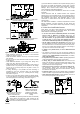
1.4 Mounting the Bracket in Place
Read Section 4 in this manual first, then decide where to install
the detector. Refer to Figure 2 and proceed according to the
following instructions.