
User's Manual

DE2411U 1
MCT/IR-252 WP S
Resettable Dual RF & IR Waterproof Transmitter User Guide
1. INTRODUCTION
The MCT/IR-252 WP S is a miniature, water-proof, resettable,
microprocessor controlled, personal transmitter designed for use in
the SpiderAlert signaling network. The transmitter is used ONLY
during emergencies involving security and safety of life, such
that when an alarm is activated, transmissions continue during
the pendency of this alarm condition. Application examples
include elderly hospital patients and emergency nurse calls. The
transmitter has two buttons, used for reporting three different
emergency events: PANIC1 (large button), PANIC2 (small button)
PANIC3 (by clicking on the two buttons simultaneously). The alarm
events are supposed to be acknowledged and reset by the person
who responds to the alarm message by holding a magnet close to
the pendant. In the case that an event is not acknowledged, a No
Response message is sent. In addition to the above-mentioned
events, the transmitter also sends low-battery and supervision
messages (when defined in DIP switch). The transmitter transmits
coded UHF signals and pulsed infrared signals simultaneously,
thereby allowing the target receiver to accurately determine the
specific point at which transmission took place in multi-storey
buildings.
Besides the regular alert mode, in which an alert message is
transmitted only once, the transmitter can be set to two additional
modes – MESSAGE CYCLE and REPEATED MESSAGE
CYCLING. In the message cycle mode, PANIC1, and PANIC2
messages are automatically repeated three times (initially 4 times),
and a no-response message follows if the message has not been
acknowledged. In the cycle repetition mode, a sequence of three
alarm messages followed by a no-response message (one cycle) is
repeated 5 times, unless the message is acknowledged sooner.
The time interval between these messages is determined by the
DIP switches (para. 3.1). When a PANIC1 message is transmitted
after an PANIC2 message has been initiated, the repeated
messages will be PANIC1 messages instead of PANIC2 messages.
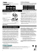
When holding an external
magnet close to the unit
pushbuttons, either from
underneath or on top, (fig. 1),
the repetitive message
transmissions stop and an
acknowledge message is sent.
Fig. 1 – Resetting Transmitter
Once the button is
depressed, the LED lights
and after approximately one
second the message is
transmitted.
It is important not to cover
the LED during the period of
time after pressing the
button. When keyed into
transmission, the transmitter
transmits its unique factory
LARGE
BUTTON
SMALL
BUTTON
BATTERY
COVER
HOLES
FOR
CHAIN
Figure 2 – MCT/IR-252 WP S
programmed, randomly selected 24-bit digital ID code. There are over
16 million code possibilities, so for all practical purposes no two
transmitters will have the same ID code. The dual-technology alert
transmissions made by the MCT/IR-252 WP
S are directed at
SpiderAlert receivers. These receivers are strategically located all
over the surveillance area, to pick up alert transmissions and report
the ID code of the transmitter whose signal was picked up.
SpiderAlert system
SLC-5UPS
Controller
PC
SR-520
RF+IR
receiver
SpiderBus
MCT/IR-252
WP
S
Figure 3 – Application Configuration
Reporting is accomplished via a two-wire bus routed to the
SpiderAlert Local Control Unit SLC-5, that collects and transfers all
data to the SpiderAlert main computer automatically displaying the
holder’s name and exact location. All units are supplied with a
chain, to be worn around the neck as a pendant transmitter.
2. SPECIFICATIONS
Frequency (MHz): 315 or 868.
IR Transmission Range: 14 m (46 ft) max. with unobstructed line
of sight (para. 5.2).
RF Transmission Range: 30-40m indoors.
Transmitter ID: 24-bit digital word, over 16 million combinations,
pulse width modulation
Message length: 36 bit.
Transmission Duration: Limited by timer to approx. 2 seconds.
Power Supply: 3V lithium battery Panasonic CR2450 or
equivalent.
Current Consumption: 3µA (standby), 10 mA (transmission).
Battery Life: 3 years for typical use.
Battery Capacity: 500mAh
Low Battery Threshold: 2.5 VDC
Operating Temperature: 0° to 50°C (32° to 122°F).
Dimensions: 39x60x18mm (1-7/16x2-3/8x5/8 In.).
Weight: 40 g (1.4 oz).
Color: Violet Transparent.
Compliance with Standards: FCC ID: GSAWTIR201, CANADA:
1467 102 270
Patents: U.S. patent 5,661,471
3. TRANSMITTER MESSAGES
3.1 Internal DIP Switch Functions
The internal DIP switches functions and their default positions (set
by the manufacturer) are detailed in table 1.
To change DIP switch settings, remove the battery as detailed in
para. 4.1 and set the required DIP switch positions. Position the
battery in place and secure the battery cover.
Table 1 - Internal DIP Switch Functions
SW # Description Default
1 Supervision ON/OFF (*) OFF
2 Cycling ON/OFF (**) ON
3 Repeat Cycling ON/OFF (***) ON
4 Retransmission Periods (****) OFF
5 Retransmission Periods (****) OFF
*Supervision type
ON - the supervision messages are transmitted every 60 minutes.
OFF– No supervision messages are transmitted.
**Message Cycling
ON – Initially 4 repetitive PANIC1 messages are transmitted
followed by a NO-RESPONSE message, after which 3 repetitive
PANIC1 messages are transmitted followed by a NO-RESPONSE
message.
OFF – a single PANIC1 message is transmitted.