MP-802 PG+ Wireless PIR Motion Detector Installation Guide Installation guidelines The reference to MP-802 PG+ throughout this manual includes the model MP-802 P9M0. CAUTION: Only qualified personnel may install this equipment. Place this device in nonhazardous indoor locations only. Important: Check the device and the entire alarm system weekly to ensure optimal performance.
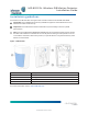
Figure 2: Optimizing detection and avoiding false alarms 1. Do not install near high-voltage electrical lines. 2. Keep away from heat sources. 3. Do not install outdoors. 4. Avoid direct sunlight. 5. Do not expose to air drafts. 6. Do not install behind partitions. 7. Do not mount on an unstable surface. 8. Install on a solid and stable surface at a height of 1.8 m to 2.4 m (6 ft. to 8 ft.) Warning! Do not obscure partially or completely the device's field of view.
Enrolling the device 1. 2. Refer to the control panel installation manual for the complete set of enrollment instructions and testing procedures. From the Installation menu, enter the Device enrollment menu and select the option to add a new device. 3. Remove the battery pull-tab to power on the device and begin the auto-enrollment process. If the battery pull-tab is not available or if the device does not automatically enroll, open the device cover to trigger the enrollment.
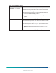
Configuring the device parameters 1. Enter the DEVICE SETTINGS menu and select the required configuration as described in the following table. Table 1: Configuration options Option Action Alarm LED Define whether the alarm LED indication will be activated. Optional settings: LED ON (default) and LED OFF. Event counter Define whether an alarm will be activated upon continued motion (low sensitivity) or upon a single alarm event (high sensitivity).
Table 1: Configuration options Option Action FREEZING < 7°C [<45°F] Define whether or not the control panel will report a freezer alert when the temperature drops below the threshold value for at least the Alert Delay duration. Alert restore will occur when the temperature rises 1°C (1.8°F) above the threshold for at least the Restore Delay duration. Note: The default threshold value for freezing is 7°C (45°F). Optional settings: See Configuring the Temperature Alerts.
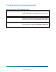
Configuring the temperature alerts You can configure the temperature alerts with the settings described in the following table. Table 2: Temperature alert configuration options Option Action Threshold Displays the last saved threshold value and provides the installer with the ability to change the value using the back or next button. Disable/Enable Define whether the panel reports an alert or not.
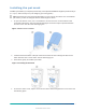
Installing the pet mask Install the pet mask if you require pet immunity. The optimal installation height for pet immunity is 2.1 m (7 ft.). Pet immunity is for pets weighing up to 38 kg (85 lb). Note: Pet immunity is not supported at heights of 2.4 m (7.87 ft.) and above. Do not install the pet mask if you are mounting the device at this height or above. 1. To open the device cover, use a screwdriver to loosen the cover screw located on the underside of the device. See A1 in the following figure.
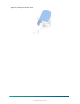
Figure 5: Closing the device cover 8 MP-802 PG+ Wireless PIR Motion Detector Installation Guide D-308439 MP-802 PG+ Rev.
Removing the pet mask Remove the pet mask if you do not require pet immunity. 1. 2. Open the device cover. See Figure 3. Remove the tabs at the side of the pet mask from both holes and gently lift the pet mask out from the bottom holes. See the following figure. Figure 6: Removing the Pet Mask 3. Close the device cover. See Figure 5. MP-802 PG+ Wireless PIR Motion Detector Installation Guide D-308439 MP-802 PG+ Rev.
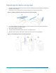
Mounting the device using tape 1. Peel the release liners off the two strips of double-sided adhesive tape and attach the tape to the back of the bracket. See Figure 7 A for flat surface mounting and B for corner surface mounting. Figure 7: Double-sided adhesive tape placement on the bracket 2. For corner surface mounting, ensure the corner mounting insert is attached to the back of the corner bracket. See Figure 10 B. 3. Mount the bracket on the wall. 4. Align the device with the bracket.
Mounting the device using screws Note: Make sure to fasten the break-away segment to the frame. If the device is forcibly removed from the wall, this segment will break away from the base, causing the tamper switch to open. 1. To mount the device on a flat surface, screw the flat bracket to the wall. See the following figure. Figure 9: Flat bracket screw installation 2. To mount the device on a corner surface, ensure the corner mounting insert is attached to the back of the corner bracket.
3. 4. Callout Component E Stopper snap F Break-away segment Screw the corner bracket to the wall. See C in the previous figure. Optional: If the installation surface does not allow for mounting the bracket with screws in the right side, screw the corner bracket using the two left side screw holes. See D in the previous figure. Important: When mounted like this, back tamper protection is not available. 5. Align the device with the bracket. See A1 in the following figure. 6.
Disassembling the device from the bracket 1. Open the device cover. See Figure 3. 2. 3. Remove the battery. Use a screwdriver to press on the stopper snap to release the device base from the bracket. See A1 in the following figure. 4. Slide the device downwards to remove it from the bracket. See A2 in the following figure. Figure 12: Disassembling the device from the bracket MP-802 PG+ Wireless PIR Motion Detector Installation Guide D-308439 MP-802 PG+ Rev.
Replacing the battery CAUTION: Risk of explosion if battery is replaced by an incorrect type. Dispose of used batteries according to the manufacturer's instructions and according to local rules and regulations. 1. Open the device cover. See Figure 3. 2. Remove the battery. See A in the following figure. Note: It is recommended to wait about 1 minute after battery removal before inserting the new battery. 3. Insert the new battery while observing battery polarity. See B in the following figure.
Local diagnostics test After power-up or closing the cover, the device automatically enters Test Mode for 15 minutes. To manually enter the devices into Test Mode refer to the Control Panel Installer Guide. 1. Before you start the test, remove the device cover from the base. See Figure 3. 2. Close the cover to return the tamper switch to its normal position. 3. 4. The device enters a 2 minute stability period. During this time the red LED blinks. Walk-test the coverage area. See the figure below.
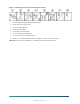
Figure 14: Coverage pattern walk test Fresnel and cylinder type lens with optical attenuation (pet mask) in the lower pattern part of the lens. Number of beams / curtains: 27 Fresnel far (54 sensitivity “beams”), 18 Cylinder mid, 10 Cylinder close. Important! Instruct the user to walk test at least once a week to verify proper function of the device. 16 MP-802 PG+ Wireless PIR Motion Detector Installation Guide D-308439 MP-802 PG+ Rev.
Specifications Frequency band 912 to 919 MHz Modulation GFSK Communication Protocol PowerG Battery Type 3 V Lithium CR-123A Panasonic, Duracell, and GP only Battery Life 6 to 8 years with typical use at room temperature 25°C (77°F) Low Battery Threshold 2.4 V at room temperature 25°C (77°F) Operating Temperature -10°C (14°F) to 50°C (122°F). Storage Temperature -20°C (-4°F) to 60°C (140°F) Relative Humidity Up to 95% non-condensing Dimensions (LxWxD) 86 mm x 63 mm x 40 mm (3.4 in. x 2.
Compliance with standards MP-802 PG+ complies with the following standards: FCC (915 MHz): 47CFR part 15.247 MP-802 P9M0 FCC Compliance Statement This device complies with FCC Rules Part 15 license-exempt standard(s). Operation is subject to two conditions: (1) This device may not cause harmful interference, and (2) this device must accept any interference that may be received or that may cause undesired operation.
About MP-802 PG+ The MP-802 PG+ is a microprocessor-controlled wireless digital PIR detector, with optional pet immunity. The device has the following features: • Fresnel and cylindrical lenses with uniform detection sensitivity throughout its operating range, up to 12 meters (39 ft). • Target Specific Imaging™ (TSI) technology is used for distinction between humans and pets weighing up to 38 kg (85lb).
Warranty Visonic Ltd. (“Seller”) warrants the Products to the original purchaser only (the “Buyer”) against defective workmanship and materials under normal use of the Products for a period of twelve (12) months from the date of shipment by the Seller. This Warranty is absolutely conditional upon the Products having been properly installed, maintained and operated under conditions of normal use in accordance with the Seller's recommended installation and operation instructions.
The SELLER shall have no liability for any death, personal and/or bodily injury and/or damage to property or other loss whether direct, indirect, incidental, consequential or otherwise, based on a claim that the Product failed to function.
©2022 Johnson Controls. All rights reserved. JOHNSON CONTROLS, TYCO and DSC are trademarks and/or registered trademarks. Unauthorized use is strictly prohibited. D-308439 MP-802 PG+ Rev.