Pow e rM a st e r-1 0 I nst a lle r Guide T ABLE OF CON T EN T S 1. INTRODUCTION .......................................................4 PowerG Technology is easy to install and maintain ................................................................4 2. SPECIFICATIONS.....................................................5 Functional.............................................................5 Wireless ................................................................6 Electrical ...........................
4.9 Arming/Disarming Options And Exit/Entry Delay ...................................................................53 4.9.1 Configuring Exit Modes ......................... 53 4.9.2 Configuring Entry Delays Duration ...... 53 4.9.3 Configuring Exit Delay Duration ........... 54 4.9.4 Enabling Quick Arm ............................... 54 4.9.5 Configuring Bypassing Zones .............. 55 4.9.6 Configuring Panic Alarm Activation ..... 56 4.9.7 Enabling Latchkey Arming .................... 56 7.
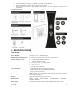
MESSAGE TO THE INSTALLER The PowerMaster-10 control panel is supplied with 3 instruction manuals: Installer Guide (this manual - for your exclusive use) User’s Guide (for your use during installation only - Must be handed over to the master user after testing the system) Accessories Guide (includes a full description of devices that are supported by the PowerMaster-10 system) Appendices A.1 and A.2 of the Installer Guide will help you prepare an installation plan.
1. INTRODUCTION The PowerMaster-10 is a user and installer-friendly, 29-zone fully-supervised wireless control system using Visonic's new revolutionary PowerG™ two-way Time Division Multiple Access (TDMA) Frequency Hopping Spread Spectrum (FHSS) technology.
Remotely review and/or change configuration and status of all peripherals Initiate remote walk test with assistance by anyone in the house Remote diagnostics of wireless signal quality for all peripherals - measure all wireless connections and reports back System Architecture: 2. SPECIFICATIONS Functional Zones Number 28 wireless zones, 1 hardwired input. Hardwired Zone Requirements 2.2 kE.O.L. resistance (max.
Siren Signals Continuous (intrusion / 24 hours / panic); triple pulse - pause - triple pulse... (fire). Siren (bell) Timeout Programmable (4 min. by default) Internal Sounder Output At least 85 dBA at 10 ft (3 m) Supervision Programmable time frame for inactivity alert Special Functions - Chime zones - Diagnostic test and event log. - Local and Remote Programming over Telephone, GSM /GPRS connections. - Calling for help by using an emergency transmitter.
Pulse Rate 10, 20, 33 and 40 pps - programmable Message to Private Phones Tone Ring Detection The unit does not support ring detection without DC voltage present on the telephone lines. Physical Properties Operating Temp. Range 14°F to 120°F (-10°C to 49°C) Storage Temp. Range -4°F to 140°F (-20°C to 60°C) Humidity 85% relative humidity, @ 30°C (86°F) Size 196 x 180 x 55 mm (7-5/8 x 7 x 2 in.
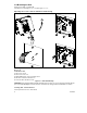
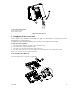
3.2 Mounting the Unit Required tool: Philips screwdriver #2. PowerMaster-10 mounting process is shown in Figure 3.1 - 3.2. Ope ning t he Cont rol Pa ne l a nd Bra c k e t M ount ing A B 3 1 A A 4 5 A. Mounting surface B. Back unit To Mount the Unit: 1. Release the screws 2. Remove the front cover 3. Mark 4 drilling points on the mounting surface 4. Drill 4 holes and insert wall anchors 5. Fasten the back unit with 4 screws Figure 3.
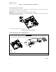
1 To Close the Control Panel: 1. Close the front cover 2. Fasten the screws Figure 3.2 - Final Closure 3.3 Supplying Power to the Unit Connect power to the PowerMaster-10 temporarily (see Figure 3.4). Alternatively, you may power up from the backup battery, as shown in Figure 3.3. Disregard any “trouble” indications pertaining to lack of battery or lack of telephone line connection. For Europe Safety Compliance: a. The model shall be installed according to the local electrical code. b.
1. Battery insertion 2. Battery connection Figure 3.3 – Connecting Power to the Control Panel Conne c t ing Pow e r t o Pa ne l Connect the power cable and close the control panel as shown below. Electrical socket-outlet shall be installed near the equipment and shall be easily accessible. WARNING! DO NOT USE AN OUTLET CONTROLLED BY A WALL SWITCH. Note: This equipment should be installed in accordance with Chapter 2 of the National Fire Alarm Code, ANSI/NFPA 72, (National Fire Protection Association).
B I D A E 1 F A. B. C. D. E. F. G. H. I. J. K. F 3 4 7 H E J RJ-31X G C 2 6 5 G K H SET LINE RJ-31X cord 8-position RJ-31X plug Gray Red Green Brown RJ-31X jack Line from street House phones Figure 3.5 – Phone Wiring This equipment is designed to be connected to the telephone network using RJ11 connector which complies with Part 68 rules and requirements adopted by ACTA and properly installed RJ31X connector. See drawing below for details.
Note: The REN is used to determine the number of devices that may be connected to a telephone line. Excessive RENs on a telephone line may result in the devices not ringing in response to an incoming call. In most but not all areas, the sum of RENs should not exceed five (5.0). To be certain of the number of devices that may be connected to a line, as determined by the total RENs, contact the local telephone company. Connection to telephone company provided coin service is prohibited.
3.7 Annual System Check Note: This system must be checked by a qualified technician at least once every three (3) years (preferably every year). The annual system check is designed to ensure proper operation of the alarm system by performing the following checks: Periodic test Arm/disarm function No trouble messages are displayed on control panel The clock displays the correct time Reporting: generating an event to be transmitted to the central station and to the user.
4. PROGRAMMING 4.1 General Guidance We recommend programming the PowerMaster-10 on the work bench before actual installation. Operating power may be obtained from the backup battery or from the AC power supply. 4.2 Entering the Installer Menu The following procedure describes how to enter the Installer Menu. To Enter the Installer Menu 1. READY 00:00 2. INSTALLER MODE ENTER CODE: CODE 3.
Chapter 5. USER SETTINGS Use to enter the USER SETTINGS menu to perform user settings. See section 4.2. FACTORY DEFLT Use to restore the control panel to factory defaults. See section 7.6. SERIAL NUMBER Use to read the serial number of the control panel. See section 7.7. START UL/DL TO EXIT Returns to first option Use to initiate the upload/download process. See Chapter 6. Use to exit from the “INSTALLER MODE” menu back to Main Menu. See section 4.3.
4.3 Navigation This mode allows you to customize the control panel and adapt its characteristics and behavior to the requirements or of the particular user. To review the options within the control panel menus, repeatedly press the button, until the desired option is displayed, then press the button. You will mainly use 5 control pushbuttons during the entire programming process: - to move one step forward in a menu. - to move one step backward in a menu. - to enter the relevant menu or confirm data.
5. INST. CODE 888 Enter the new 4-digit Installer Code (8888 or 9999) at the position of the blinking cursor and then press .* NEW INST. CODE * The default Installer Code is 9999. If your system uses MASTER CODE, you should proceed to setting the MASTER INSTALLER code in section 4.4.2 by pressing the button, or press the button to take you to " TO EXIT". Note: Installer Code should never be programmed as “0000”. Doing so will lock the user out of the installer menu! 4 .4 .
4 .4 .3 Se t t ing U se r Code s For detailed instructions on setting user codes, refer to the PowerMaster-10 user guide "Menus and Functions". 4 .4 .4 Ena bling U se r Pe rm it for I nst a lle r Ac c e ss User Permission enables you to determine whether access to the INSTALLER MODE requires user permission. Access to the installer menu, in PowerMaster-10 that has "User Permission" enabled (for example, in UK) is via the last menu in the user menu. This option can be changed, if necessary.
To Configure Permissions for System Reset after an Alarm Event Repeat steps 1 to 4 of section 4.2 "Entering the Installer Menu". 1. 2. DEFINE PANEL 3. 01:ENTRY DELAY 1 or 4. 25:RESET OPTION 5. user reset Select between "user reset" (default), "engineer reset" and "anti code reset". 25:RESET OPTION You can now press the or in "DEFINE PANEL" or press the EXIT". button to program any other menu button to take you to " TO 4 .4 .
4.5 Zones / Devices 4 .5 .1 Ge ne ra l Guida nc e The ZONES / DEVICES mode enables the following functions: - Defining default parameters common for each devices family. - Adding new devices (enrolling) and defining their zones name, zone type and chime zone. - Deleting devices. - Modifying devices parameters. - Reviewing devices parameters. Enrolling can be performed for Keyfobs (multi-button), wireless detectors, wireless sirens and repeaters.
DEVICE ENROLLED K01:Keyfob Z01:Motion Sens ……….. S01:Siren The PowerMaster-10 display reads "DEVICE ENROLLED" (or "ID accepted" if the device was enrolled manually by entering the ID number) and the PowerMaster-10 display will then change to "K01:Keyfob / Z01:Motion Sens / S01:Siren depending on the type of enrolled device". However, if the device was previously enrolled in the system, the PowerMaster-10 display reads "ALREADY ENROLLED".
To understand the behavior of each zone, see section 4.5.2.3 Zone Types. 3.Home Delay 6. Z01:SET CHIME Press 7. to change chime settings or press the button to skip. Chime off…. 8. or Select between "Chime off" and "melody-chime". Note: In "melody chime" mode when a chime zone is triggered, chime melody is heard. melody-chime 9. Z01:DEV SETTINGS 10. NEXT device * MODIFY SAME Dev. * EXIT Enrollment * 11. 12.
Emergency Zones: You can provide incapacitated, sick or elderly people with a miniature single-button transmitter to be carried on the neck like a pendant or to be worn on the wrist like a watch. In distress situations, they can press the button on their transmitter, causing the PowerMaster-10 to send an emergency call to the Monitoring Station or to private telephones designated by the installer.
Child room Closet (UK: Conservatory) Den (UK: Playroom) Dining room Downstairs Emergency Fire Front door Garage Garage door Guest room Hall Kitchen Laundry room Living room Master bath Master bdrm Office (UK: Study) Upstairs Utility room Yard (UK: Garden) Custom 1 Custom 2 Custom 3 Custom 4 Custom 5 4 .5 .3 Adding Wire d Z one s Required tools: Cutter and slotted screwdriver - 3 mm blade. PowerMaster-10 wiring is shown in Figure 4.1. CABLES ROUTING GUIDE A B C 1 2 A. Cables entry options B.
ZONE WIRING A B 2.2k 2.2k C A. ZONE B. TAMPER C. ALARM Note: Do not use mains cable other than that supplied by the manufacturer (3 m long). Figure 4.1 - Wiring 4 .5 .4 De le t ing a De vic e C. To Delete a Device Repeat steps 1 to 3 in section 4.5.2 "Adding a Wireless Device". 1. ADD NEW DEVICES 2. DELETE DEVICES 3. CONTACT SENSORS 4. or Select the type of device to be deleted.
Z03:Motion Sens 7. (OFF) to delete 8. MOTION SENSORS The device is deleted from the PowerMaster-10 system. When exiting "ZONES / DEVICES" menu the PowerMaster-10 system displays the number of devices that need to be updated, as follows: DEV UPDATING NNN. You can now press the button to delete the device of the same type, or press the button to delete a different device, or press the button to take you to " TO EXIT". 4 .5 .5 M odifying a De vic e D.
3. Home Delay 11. Z01: SET CHIME Press skip. 12. to change chime settings or press the button to Chime off…. or 13. Select between "CHIME OFF" and "melody-chime". Note: In "melody chime" mode when a chime zone is triggered, chime melody is heard melody-chime 14. You can now press the button to modify the next device of the same type, or press the button to configure the parameters of the device (see the Accessories Guide for instructions), or press the button to take you to " TO EXIT". 4 .5 .
8. 9. ENROLL NOW or Enroll the new device, or, enter the last 4 digits of the ID number of the new device.* ENTR ID:100-xxxx DEVICE ENROLLED The PowerMaster-10 display will read the result.** Z01: Contact ID No. 100-2332 * If the device was previously enrolled in the system, the PowerMaster10 display reads "ALREADY ENROLLED" and then switches to the name of the device alternating with the ID number of the device. If the device ID number is invalid the PowerMaster-10 display reads "WRONG ID No".
6. For reviewing parameter configurations refer to the PowerMaster-10 Accessories Guide in section "MODIFY DEVICE SETTINGS" of the desired device. At the end of the procedure you can press the button and perform the same procedure for a different device or you can press the button to take you to “ TO EXIT”. 4.6 Siren Configuration 4 .6 .1 Configuring t he Le ngt h of T im e t he Be ll is a llow e d t o Func t ion Here you select the length of time the bell (or siren) is allowed to function upon alarm.
24:PIEZO SIREN 4. piezo siren ON 5. or Select between "piezo siren ON" and "piezo siren OFF". 6. 24:PIEZO SIREN You can now press the or menu in "DEFINE PANEL" or press the TO EXIT". button to program any other button to take you to " 4 .6 .3 Configuring t he Pe riod of St robe Light Ac t iva t ion Here you can define the period of strobe light activation when the siren is in alarm state. Options: 5 minutes, 10 minutes, 20 minutes (default), 40 minutes and 60 minutes.
27:SIREN ON LINE 4. disable on fail Select between "disable on fail" and "enable on fail". or 5. 6. 27:SIREN ON LINE You can now press the or menu in "DEFINE PANEL" or press the TO EXIT". button to program any other button to take you to " 4.7 Event Reporting Configuration 4 .7 .1 Ge ne ra l The PowerMaster-10 system uses an IP platform that supports GSM and GPRS cellular communication and broadband to forward all events received at the control panel to the monitoring station. 4 .7 .
12. DIAL METHOD 13. GSM KEEP ALIVE Here you prevent the GSM Service provider from disconnecting the GSM line if the user has not initiated any outgoing telephone calls during the last 28 days. 14. disable 15. Select between "disable" and "every 28 days". or 16. GSM KEEP ALIVE You can now press the button to revert to the "AREA CODE" menu, or press the button to take you to " TO EXIT". 4.7.2.
GSM REPORT 12. Here you determine whether the alarm system will report events to the Monitoring Station via the SMS Channel. SMS REPORT 13. disable 14. or Select between "disable" and "enable". 15. SMS REPORT 16. GPRS APN 17. 18. APN NAME Enter the name of the APN Access Point used for the internet settings for the GPRS (up to 40 digits). Note: The table at the end of this section provides a list of the keys used by the PowerMaster-10 editor. 19. GPRS APN 20. GPRS USERNAME 21. 22.
PIN CODE 32. FORCE HOME NTWK. Here you determine whether to force the SIM card to use the home network only and not to select another network in case the home network cannot be found. 33. disable 34. or Select between "disable" and "enable". 35. FORCE HOME NTWK. 36. SESSION TIMEOUT Here you determine whether the control panel will stay continuously connected via GPRS communication, or, temporarily connected to receive event reports only. 37. off on timeout 38.
separator between events reported to Monitoring Station 1 and events reported to Monitoring Station 2. Messages are divided by type into the following groups: Group Abbr. Events Reported Alarms Open/close Alerts Maintenance alrm o/c Alrt - Fire, Burglary, Panic, Tamper Arming AWAY, Arming HOME, Disarming No-activity, Emergency, Latchkey Low-battery AC failure "Alarm" group has the highest priority and "Alert" group has the lowest priority.
following instructions: REPORT EVENTS 1. 1st RPRT METHOD Here you define the 1st priority of method used to report events. 2. disable 3. Select between "disable", "cellular", "broadband" and "PSTN". or 4. 1st RPRT METHOD 5. 2nd RPRT METHOD Here you define the 2nd priority method used to report events. If the method defined to report events in the 1st priority fails, the control panel will attempt to report using the method defined in the 2nd priority. 6. disable 7.
4.7.3.3 Configuring Account Numbers to be Reported to the Monitoring Station Continue below from the previous section or repeat steps 1 to 4 of section 4.7.3.1 before continuing with the following instructions: REPORT EVENTS or 1. RCVR 1 ACCOUNT# Here you enter the number that will identify your specific alarm control system to the 1st Monitoring Station. The number consists of 6 hexadecimal digits. 2. 1st acc. #001234 1st RCVR ACC. NO. 3. Enter the first receiver account number. 4. RCV 1 ACCOUNT# 5.
Enter the telephone number of the second PSTN/GSM receiver (for further details see the table at the end of this section). 6. PSTN/GSM RCVR 2 7. IP RCVR 1 Here you enter the IP address of the IP receiver that is located in the 1st Monitoring Station. 000.000.000.000 Enter the IP address of the first IP receiver (for further details see the table at the end of this section). 8. 9. IP RCVR 1 10. IP RCVR 2 Here you enter the IP address of the IP receiver that is located in the 2nd Monitoring Station.
Hex.Digit A Keying Sequence <#> <0> D <#> <3> E F <#> <4> <#> <5> Code Significance Applicable only at the beginning of a number - the dialer waits 10 seconds or waits for dial tone, whichever comes first and then dials. Applicable only at the beginning of a number - the dialer waits 5 seconds for dial tone and goes on hook if none is received.
1. or PSTN RPRT RETRY Here you determine the number of times the communicator will dial the Monitoring Station’s number via PSTN. 2. 4 attempts 3. Select between "2 attempts", "4 attempts", "8 attempts", "12 attempts" and "16 attempts". or 4. PSTN RPRT RETRY 5. GSM RPRT RETRY Here you determine the number of times the communicator will try to report via a cellular group (GPRS, GSM and SMS) to the Monitoring Station. 6. 4 attempts 7.
4. AUTO TEST CYCLE Here you determine the time interval between consecutive telephone line test messages sent to the Monitoring Station. The control panel performs this at regular intervals to verify proper communications. 5. test OFF 6. Select between "test OFF", "test every 1 d", "test every 2 d", "test every 5 d", "test every 7 d", "test every 14 d", "test every 30 d" and "test every 5 h". or 7. AUTO TEST CYCLE 8. LINE FAIL REPORT 9.
20. broadband 21. LINE FAIL REPORT You can now press the button to take you to the "PSTN UP/DOWN" menu (see Configuring Remote Programming Access Permissions), or press the button to take you to " TO EXIT". 4.7.3.8 Configuring the Event Types to be Reported to the Monitoring Station Continue below from the previous section or repeat steps 1 to 4 of section 4.7.3.1 before continuing with the following instructions: REPORT EVENTS 1.
14. disable 15. Select between "disable", "rep. after 7d", " rep. after 14d ", " rep. after 30d", and "rep. after 90d". or 16. SYS INACT REPORT You can now press the button to take you to the "REPORT EVENTS" menu (see section 4.7.2.1), or press the button to take you to " TO EXIT". 4 .7 .4 Configuring Eve nt Re port ing t o U se rs A. To Enable Report to Users Repeat steps 1 to 4 of section 4.2 "Entering the Installer Menu". 1. DEFINE COMM. 2. 1:PSTN/GSM or 3. 4:PRIVATE REPORT 4.
You can now press the REPORT" menu, or press the EXIT". button to take you to the "VOICE button to take you to " TO C. To Configure Event Types to be Reported to User 8. VOICE REPORT 9. 1st private tel# 10. 11. 1st PRIVATE TEL. NO. Enter the first private telephone number (including area code, if required) of the private subscriber to which the system will report the event groups defined in Report To Private. 12. 1st private tel# 13. 2nd private tel# 14. 15. 2nd PRIVATE TEL. NO.
3 attempts 27. or Select between "1 attempt", "2 attempts", "3 attempts" and "4 attempts". Attention! A maximum of 2 dialing attempts is permitted by the Australian Telecommunication Authority. 28. Redial attempts 29. Tel. acknowledge Here you determine whether the system will use the single acknowledge or the all acknowledge mode when reporting to private telephones.
42. 2nd SMS tel# 43. 3rd SMS tel# 44. 3rd SMS TEL. NO. Enter the third SMS phone number (including area code, 16 digits max.) to which pre-selected event types will be reported. 45. 3rd SMS tel# 46. 4th SMS tel# 47. 48. 4th SMS TEL. NO. Enter the fourht SMS phone number (including area code, 16 digits max.) to which pre-selected event types will be reported. 49. 4th SMS tel# You can now press the button to take you to the "1st private tel#" menu (see step C.
14:CROSS ZONING You can now press the or menu in "DEFINE PANEL" or press the TO EXIT". button to program any other button to take you to " 4 .8 .2 Configuring Sw inge r St op Here you determine the number of times each zone is allowed to initiate an alarm within a single arming/disarming period (including tamper & power failure events of detectors, PowerMaster-10, wireless siren, etc.).
3. or 21:NOT ACTIVE 4. no act disable 5. or Select between "no act disable", "3 h", "6 h", "12 h", "24 h", "48 h", and "72 h". 6. 21:NOT ACTIVE You can now press the or menu in "DEFINE PANEL" or press the TO EXIT". button to program any other button to take you to " 4 .8 .4 Configuring Ala rm Ca nc e l Pe riod Here you determine the ”cancel alarm” period that starts upon reporting an alarm to the Monitoring Station.
To Configure the Power Failure Threshold Period Repeat steps 1 to 4 of section 4.2 "Entering the Installer Menu". 1. DEFINE PANEL 2. 01:ENTRY DELAY 1 or 3. 34:AC FAIL REP 4. 5 minutes Select between "5 minutes", "30 minutes", "60 minutes", and "180 minutes". or 5. 6. 34:AC FAIL REP You can now press the or menu in "DEFINE PANEL" or press the TO EXIT". button to program any other button to take you to " 4 .8 .
4 .8 .7 Configuring a Confirm e d Ala rm Here you determine that if 2 successive alarms will occur during a specific period, the second alarm will be considered as a confirmed alarm for confirmed alarm reporting, (see par. 4.6.3.2 "Configuring the Event Types to be Reported"). Options: disable (default in USA), 30 min., 45 min., 60 min. (default), or 90 min. To Configure a Confirmed Alarm Repeat steps 1 to 4 of section 4.2 "Entering the Installer Menu". 1. DEFINE PANEL 2. 01:ENTRY DELAY 1 3.
You can now press the or menu in "DEFINE PANEL" or press the TO EXIT". button to program any other button to take you to " 4 .8 .9 Configuring t he J a m m ing De t e c t ion Here you determine whether jamming (interfering transmissions, on the radio channel used by the system) will be detected and reported or not. If a jam detection option is selected, the system does not allow arming under the relevant jamming conditions.
To Configure whether a missing device causes the system to become "NOT READY" Repeat steps 1 to 4 of section 4.2 "Entering the Installer Menu". 1. DEFINE PANEL 2. 01:ENTRY DELAY 1 3. or 16:NOT READY 4. normal 5. or Select between "normal", and "in supervision". 6. 16:NOT READY You can now press the or menu in "DEFINE PANEL" or press the TO EXIT". button to program any other button to take you to " 4 .8 .
4.9 Arming/Disarming Options And Exit/Entry Delay 4 .9 .1 Configuring Ex it M ode s Here you determine exit delay mode options. Three types of exit delay modes are available: restart exit - Exit delay restarts when the door is reopened during exit delay. The restart occurs once only. Restarting the exit delay is helpful if the user re-enters immediately after going out to retrieve an item that he left behind.
entry dly1 30s 4. or Select between "entry dly1 00s", "entry dly1 15s", "entry dly1 30s", "entry dly1 45s", "entry dly1 60s", "entry dly1 3m" and "entry dly1 4m".** 5. 09:EXIT MODE * Press the button for "02:ENTRY DELAY 2". ** In the "02:ENTRY DELAY 2" menu, the PowerMaster-10 display will read "entry dly2…". You can now press the or button to program any other menu in "DEFINE PANEL" or press the button to take you to " TO EXIT". 4 .9 .
Repeat steps 1 to 4 of section 4.2 "Entering the Installer Menu". 1. DEFINE PANEL 2. 01:ENTRY DELAY 1 or 3. 07:QUICK ARM 4. quick arm OFF 5. Select between "quick arm ON", and "quick arm OFF". or 6. 07:QUICK ARM You can now press the or menu in "DEFINE PANEL" or press the TO EXIT". button to program any other button to take you to " 4 .9 .
4 .9 .6 Configuring Pa nic Ala rm Ac t iva t ion Here you determine whether the user will be allowed to initiate a panic alarm by simultaneous pressing of either the two panic buttons (on the keypad / wireless commander) or away + home (on a keyfob transmitter). Audible panic activates the siren and simultaneously transmits a message via telephone. Silent panic only transmits a message via telephone. The options are: silent panic, audible panic (default) and disable panic.
You can now press the or menu in "DEFINE PANEL" or press the TO EXIT". button to program any other button to take you to " 4.10 User Interface Customization 4 .1 0 .1 Ena bling T rouble Be e ps Under trouble conditions, the sounder emits a series of 3 short beeps once per minute. Here you determine whether this special beeping sequence will be active, inactive, or just inactive at night (the range of “night” hours is defined in the factory but is usually from 8 PM until 7 AM).
enable beeps 5. Select between "enable beeps", "off when home" and "disable beeps". or 6. 10:PIEZO BEEPS You can now press the or menu in "DEFINE PANEL" or press the TO EXIT". button to program any other button to take you to " 4 .1 0 .3 Ena bling t he Ba c k Light Here you determine whether the keypad back lighting will remain on at all times or will turn on when a key is pressed and turn off within 10 seconds if no further keystrokes are sensed.
2. 01:ENTRY DELAY 1 3. or 29:DISARM OPTION 4. any time 5. or Select between "any time", "on entry wrless", "entry + away kp" and "on entry all". 6. 29:DISARM OPTION You can now press the or menu in "DEFINE PANEL" or press the TO EXIT". button to program any other button to take you to " 4 .1 0 .
4 .1 0 .6 Ena bling t he M e m ory Prom pt Here you determine whether the user will receive indication that an alarm has been activated. Available options are: enable (default) and disable. To Enable the Memory Prompt Repeat steps 1 to 4 of section 4.2 "Entering the Installer Menu". 1. DEFINE PANEL 2. 01:ENTRY DELAY 1 or 3. 28:MEMORY PROMPT 4. enable 5. Select between "enable" and "disable". or 6. 28:MEMORY PROMPT You can now press the or menu in "DEFINE PANEL" or press the TO EXIT".
4.11 DEFINE CUSTOM LOCATIONS This mode allows you to define up to 5 locations (in addition to the locations that can be defined in the ZONES / DEVICES mode - see par. 4.4). To Define Custom Locations Repeat steps 1 to 4 of section 4.2 "Entering the Installer Menu". 1. DEFINE CUSTOM 2. CUST. ZONES NAME 3. EDIT USER TERM 1 4. Custom 1 Enter the first custom location. Note: The table at the end of this section provides a list of the keys used by the PowerMaster-10 editor. 5.
4 .1 2 .2 De fine PGM For the PGM output, you can select disable, turn on, turn off or pulse active (turn on for predefined period, selected by PULSE TIME), as follows: ARM AWAY (upon AWAY arming). ARM HOME (upon HOME arming). DISARM (upon disarming). MEMORY (activated upon registration of an alarm in the memory, turned off upon memory clearing). DELAY (during exit / entry delays). KEYFOB (upon AUX button pressing in the keyfob transmitter).
13. PGM: BY ARM HOME 14. PGM: BY DISARM 15. disable 16. or Select between "disable", "turn active". ON", "turn OFF" and "pulse Select between "disable", "turn active". ON", "turn OFF" and "pulse Select between "disable", "turn active". ON", "turn OFF" and "pulse 17. PGM: BY DISARM 18. PGM: BY MEMORY 19. disable 20. or 21. PGM: BY MEMORY 22. PGM: BY DELAY 23. disable 24. or 25. PGM: BY DELAY 26. PGM: BY KEYFOB 27. disable 28.
output. 33. disable 34. Select between "disable", "turn ON", "turn OFF", "pulse active" and "toggle". or 35. a - zone 36. b - zone 37. b – zone Z:00 Enter the number of the second zone that you designate for activating this output. 38. disable 39. Select between "disable", "turn ON", "turn OFF", "pulse active" and "toggle". or 40. b - zone 41. c - zone 42. c – zone Z:00 Enter the number of the third zone that you designate for activating this output. 43. disable 44.
B. To Configure PGM Lighting Devices in Alarm Conditions and To Set Daytime Limits of Lighting Devices Repeat steps 1 to 4 of section 4.2 "Entering the Installer Menu". 1. DEFINE OUTPUTS 2. DEFINE PGM 3. PGM: GENERAL DEF 4. FLASH ON ALARM 5. no flash or 6. Select between "no flash" and "all light flash". 7. FLASH ON ALARM 8. LOCKOUT TIME 9. start – HH:MM 10. TIME 07:00A Enter the time at which you wish the lockout state to begin (usually at dawn).
4.13 Configuring Remote Programming Access Permissions Repeat steps 1 to 4 of section 4.2 "Entering the Installer Menu". 1. DEFINE COMM. 2. 1:PSTN/GSM 3. 3:C.S. REPORTING 4. REPORT EVENTS 5. or PSTN UP / DOWN 6. Remote access Here you give or deny permission to access the system and exercise control from a remote telephone. 7. rem. access ON 8. or Select between "rem. access ON" and "rem. access OFF" 9. Remote access 10. Mast.
17. any time or 18. Select between "any time" and "when system OFF". 19. Upload option 20. Up/Download tel# Here you enter the telephone number (up to 16 digits) of the UL/DL server. Note: Only for use of control panels monitored by compatible Monitoring Stations. Leave empty if not used. 21. Enter the upload/download software telephone number. 22. Up/Download tel# 23. PSTN UP / DOWN 24. GPRS UP / DOWN 25. My SIM Tel.# Here you enter the PowerMaster-10 SIM card telephone number.
Enter the second IP receiver telephone number. 33. 2nd caller ID# 34. GPRS UP / DOWN You can now press the button to take you to the "RPRT CNFRM ALARM" menu (see section 4.7.3.8), or press the button to take you to " TO EXIT". 5 DIAGNOSTIC TEST This mode allows you to test the functionality of all devices of the system and to receive / review information regarding the received signal strength. Communication between system components can also be tested and detailed information is reported.
Note: "Zxx" indicates the type of device and device number that is being tested. "NNN" indicates the number of devices that have not yet been tested. At this stage if any key is pressed the PowerMaster-10 display will read " TO END" alternating with " TO CONTINUE". Press the button to stop the current test and jump to the next test, or, press the button to continue the test, or, press the button to exit. At the end of the testing procedure the PowerMaster-10 display will read "SHOW ALL DEVICES".
Z01 24Hr: EARLY After testing the PowerMaster-10 display will then automatically change to read the average level for the last 24 hours (for stationary devices) or the number of activations that the control panel has received (for keyfobs). The signal strength indications are as follows: "STRONG"; GOOD"; "POOR"; "1-WAY" (the device operates in 1-way mode, or, the "NOW" communication test failed); "NO COM.
5 .1 .4 Displa ying Signa l St re ngt h I ndic a t ion of RF De vic e s Repeat steps 1 to 4 of section 4.2 "Entering the Installer Menu". 1. DIAGNOSTICS 2. WL DEVICES 3. TEST ALL DEVICES or 4. SHOW RF PROBLEMS 5. Z01: 24hr: GOOD The PowerMaster-10 display switches between the average signal strength indication for the last 24 hours and the current signal strength indications of the first device type. Z01: NOW: NOT Press the button to view the signal strength indications for the next RF device type.
PLEASE WAIT… UNIT IS OK See the table below for a complete list of possible GSM/GPRS messages. If there are no wireless devices enrolled in the PowerMaster-10 system, the PowerMaster-10 display reads "NO DEVICES". ** When the button is pressed the test result takes up to 4 min. before it is displayed, depending on the severity of the failure.
See the table below for a complete list of possible LAN messages. If there are no wireless devices enrolled in the PowerMaster-10 system, the PowerMaster-10 display reads "NO DEVICES". ** When the button is pressed the test result takes up to 4 min. before it is displayed, depending on the severity of the failure. Pressing the or buttons at any stage in the procedure will take you to “ TO EXIT” or pressing the button at the end of the procedure will take you to the "LAN RESET OPTION" menu.
To reset the PowerLink Broadband Module 5. REBOOT To reset all LAN setting definitions (does not reset Monitoring Station IP definitions) 6. FACTORY DEFIN. 7. FACTORY DEFIN. If there are no wireless devices enrolled in the PowerMaster-10 system, the PowerMaster-10 display reads "NO DEVICES". Pressing the or buttons at any stage in the procedure will take you to “ TO EXIT” or pressing the button at the end of the procedure will take you to the "WL DEVICES" menu.
Pressing the or buttons at any stage in the procedure will take you to “ TO EXIT”. 7. MAINTENANCE 7.1 Handling System Troubles Fault What it means Solution 1-WAY The control panel cannot configure or control the device. Battery consumption increases. i) Make sure the device is physically present. ii) Check the display for device faults, for example, low battery. iii) Use RF diagnostics to check the current signal strength and during the last 24 hours.
Fault What it means Solution SIREN AC FAILURE There is no power to the siren Make sure that the AC power supply is connected properly AC FAILURE There is no power to gas sensor Make sure that the AC power supply is connected properly GSM NET FAIL The GSM communicator is not able to connect to the cellular network. i) Move the Panel and GSM unit to another location.
7.5 Replacing/Relocating Detectors Whenever maintenance work involves replacement or re-location of detectors, always perform a full diagnostic test according to section 5. Remember! A "poor" signal is not acceptable, as stated at the end of the introduction to the test procedure. 7.6 Restoring Factory Defaults If you want to reset the PowerMaster-10 parameters to the factory default parameters, you should enter the installer menu and perform the "FACTORY DEFLT" function, as detailed below.
8 READING THE EVENT LOG Events are stored in the event log. You can access this log and review the events, one by one. If the event log fills up completely, the oldest event is deleted upon registration of each new event. The date and time of occurrence are memorized for each event. When reading the event log, events are shown in chronological order - from the newest to the oldest. Access to the event log is provided by pressing the button and not through the installer’s menu.
APPENDIX A. Detector Deployment & Transmitter Assignments A1. Detector Deployment Plan Zone No. 1 Zone Type Sensor Location or Transmitter Assignment (in non-alarm or emergency zones) Chime (Yes / No) 2 3 4 5 6 7 8 9 10 11 12 13 14 15 16 17 18 19 20 21 22 23 24 25 26 27 28 29 (*) 30 (*) Zone Types: 1 = Interior follower 2 = Perimeter 3 = Perimeter follower 4 = Delay 1 5 = Delay 2 6 = 24 h silent 7 = 24 h audible 8 = Non-alarm 9 = Emergency 10 = Interior 11 = Home / delay.
A2. Keyfob Transmitter List No. Transmitter Data Type Holder 1 2 3 4 5 6 7 8 AUX button Assignments Skip exit delay or Arming “instant” Indicate the desired function (if any) Skip exit delay Arming “instant” A3. Emergency Transmitter List Tx # Transmitter Type Enrolled to Zone Name of holder 1 2 3 4 5 6 7 8 9 10 A4.
APPENDIX B. Event Codes B1.
Alarms Zone # 1 2 3 4 5 6 7 8 9 10 11 12 13 14 15 16 17 18 19 20 21 22 23 24 25 26 27 28 29 1 digit 4 2nd 1 digit 4 2 4 3 4 4 4 5 4 6 4 7 4 8 4 4 4 4 4 4 4 9 A B C D E F 2 3 4 5 6 7 8 9 10 11 12 13 14 15 16 17 18 19 20 21 22 23 24 25 26 27 28 29 st 5 1 5 2 5 3 5 4 5 5 5 6 5 7 5 8 5 5 5 5 5 5 9 A B C D E Restorals Zone # 1 1st digit C C C C C C C C C C C C C C C D D D D D D D D D D D D D D 2nd 1 2 3 4 5 6 7 8 9 A B C D E F 1 2 3 4 5 6 7 8 9 A B C D E digit Supervisory
Trouble Event Fuse Fuse Jamming Jamming AC AC Fail Restore Restore Failure Restore CPU Low Battery CPU Low Battery Restore CP Tamper 1st digit 2 2 2 2 1 1 1 1 1 2nd digit C D E F 1 2 3 4 6 Event CP Tamper Restore No Active COMM. & LINE Restore Enter Test Exit Test Auto Test 1st digit 1 1 1 1 1 1 2nd digit 7 8 A D E F B4.
APPENDIX C. Glossary This list of terms is arranged in alphabetical order. Any term indicated by cursive (italic) letters within the explanatory text can be looked up separately. Abort Period: When an alarm is initiated, the internal sounder is activated first for a limited period of time which is the abort period set by the installer. If you cause an alarm accidentally, you can disarm the system within the abort period before the real sirens start and before the alarm is reported to the remote responders.
To disarm the system without causing an alarm, use your control keypad (which is normally accessible without disturbing a perimeter zone) or use a keyfob transmitter. Latchkey: The Latchkey mode is a special arming mode in which designated "latchkey users" will trigger a "latchkey message" to be sent to a telephone or a pager when they disarm the system. For example, if a parent wants to be sure that their child has returned from school and disarmed the system.
APPENDIX D. DEFAULT AND PROGRAMMED ZONE DEFINITIONS Zone No.
Industry Canada Declaration This product meets the applicable Industry Canada technical specifications/Le présent materiel est conforme aux specifications techniques appliables d’Industrie Canada. The Ringer Equivalence Number is an indication of the maximum number of devices allowed to be connected to a telephone interface.
WARRANTY Visonic Limited (the “Manufacturer") warrants this product only (the "Product") to the original purchaser only (the “Purchaser”) against defective workmanship and materials under normal use of the Product for a period of twelve (12) months from the date of shipment by the Manufacturer.